
Operation Manual


Settings via software
Operating Instructions 610-10/630-10 - 00.0 - 01/2016 49
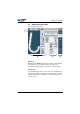
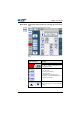
5.3 Operating mode MAN
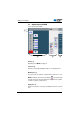
Fig. 26: Operating mode MAN
Header (1)
Operating mode MAN is displ
ayed.
Left pane (2)
Buttons for manually inputting the fullness are displayed here.
Middle pane (3)
This pane holds the symbols of all parameters that can be set in
MAN
operating mode as well as the display of the path length
already sewn in mm The gray fields above the parameter symbols
show the respective current values.
Right pane (4)
Another user interface or another operating mode can be selected
he
re.
②③④
①