
Operation Manual
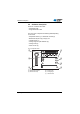
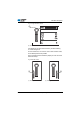


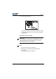
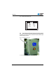
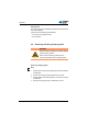

Table Of Contents
- 1 About these instructions
- 1.1 For whom are these instructions intended?
- 1.2 Representational conventions – Symbols and characters
- 1.3 Other documents
- 1.4 Liability
- 1.4.1 Transportation
- 1.4.2 Intended use
- 2 Performance description
- 2.1 Features
- 2.2 Declaration of conformity
- 2.3 Additional equipment
- 2.4 Technical data
- 3 Safety
- 3.1 Basic safety instructions
- 3.2 Signal words and icons used in warnings
- 4 Machine description
- 4.1 Control panel
- 4.2 Software description
- 4.2.1 Structure
- 4.2.2 Modes of operation
- 5 Operation
- 5.1 Switching the machine on and off
- 5.2 Activating and deactivating threading mode
- 5.3 Using threads and gimp threads
- 5.4 Removing and fitting clamping plates
- 5.5 Swiveling the sewing machine up and down
- 5.6 Threading the needle thread
- 5.7 Threading the looper thread
- 5.8 Threading the gimp thread
- 5.9 Adjusting the thread tension
- 5.9.1 Adjusting the needle thread tension
- 5.9.2 Setting the looper thread tension
- 5.10 Changing the needle
- 5.11 Changing the blade
- 5.12 Sewing
- 5.12.1 Sewing using the push buttons
- 5.12.2 Sewing with the foot pedal
- 5.13 Customer service
- 6 Maintenance
- 6.1 Inspection
- 6.2 Cleaning
- 6.3 Lubricating
- 6.4 Changing the cutting blocks and blade
- 6.4.1 Sub-class without multiflex
- 6.4.2 Sub-class with multiflex
- 7 Setup
- 7.1 Checking the scope of delivery
- 7.2 Removing the transport locks
- 7.3 Installing the frame
- 7.4 Fitting the table plate
- 7.5 Using the ring bolt
- 7.6 Securing the reel stand
- 7.7 Securing the frame
- 7.8 Setting the working height
- 7.9 Fitting the controller
- 7.10 Electrical connection
- 7.11 Equipotential bonding
- 7.12 Installing the suction container
- 7.13 Connecting the pneumatic system
- 7.14 Setting the operating pressure
- 7.15 Lubrication
- 7.16 Topping up the oil
- 7.17 Adjusting the material edge stops
- 7.18 Carrying out a test run
- 8 Software settings
- 8.1 User level
- 8.1.1 Basic operation
- 8.1.2 Single buttonhole mode
- 8.1.3 Sequential mode
- 8.1.4 Adjusting the cutting length
- 8.1.5 Adjusting the thread tension
- 8.1.6 Adjusting the cutting mode
- 8.1.7 Resetting the piece counter
- 8.2 Buttonhole programming
- 8.3 Sequence programming
- 8.3.1 Deleting a buttonhole at the end of a sequence
- 8.3.2 Adding a buttonhole at the end of a sequence
- 8.3.3 Inserting a buttonhole within a sequence
- 8.3.4 Switching off sequential mode
- 8.4 Service mode
- 9 Decommissioning
- 10 Disposal
- 11 Troubleshooting
- 11.1 Information messages
- 11.2 Error messages
- 12 Glossary
- 13 Appendix

Operation
Operating Instructions 581 - 00.0 - 02/2015 37
Gimp threads
The purpose of gimp is to stabilize the buttonhole and at the same
time make it flexible.
It should have the following characteristics:
• not too thick, but supple and firm
• even thickness
5.4 Removing and fitting clamping plates
Removing clamping plates
Step
1. Slightly raise the right clamping plate (2) at the back and pull
it backwards.
2. Remove the clamping plate (2) sideways to the right.
3. Slightly raise the left clamping plate (1) at the back and pull
it backwards.
4. Remove the clamping plate (1) sideways to the left.
WARNING
Risk of puncture wounds from sharp objects!
Severe injuries possible.
Remove and fit clamping plates when the
machine is switched off or in threading mode.