
Troubleshooting guide


9
pletes the installation steps.
Conduct a final inspection to
insure that all joints are se-
cure, the system is properly
supported, and is mechani-
cally sound. Especially verify
that the one-inch clearance
to combustibles requirement
has been met, and that ad-
equate combustion air will be
furnished to the appliance.
BUCKET SUPPORT
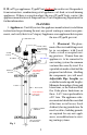
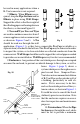
1. Description. The
Bucket Support (shown in Figure 13) is
for properly supporting the B-vent be-
tween 16 or 24-inch O.C. joists or
rafters, or for providing a transition fit-
ting
be-
tween
Dura-
Con-
nect
Single Wall Connector and the B-vent Pipe
Sections. A maximum of 20 feet of Type B
Gas Vent may be supported. Note that the
Bucket Support must be installed prior to the
sheetrock.
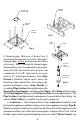
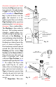
2. Assembly. After you have deter-
mined where the B-vent should be located,
assemble the Bucket Support and Brack-
ets. Nail the assembly to the bottom side of
the joist material as shown in Figure 14.
After the Support Bucket is in place, scribe
and cut out a hole in the sheet rock 1/8"
larger than the diameter of the Bucket, and
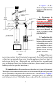
GAS VENT SYSTEMS USING VENT CAPS LISTED BY UNDERWRITER’S
LABORATORIES MAY TERMINATE IN ACCORDANCE WITH THIS VENT
TERMINATION TABLE
ROOF PITCH MINIMUM HEIGHT
FEET METERS
FLAT TO 7/12 1 0.3
OVER 7/12 TO 8/12 1.5 0.46
OVER 8/12 TO 9/12 2 0.61
OVER 9/12 TO 10/12 2.5 0.76
OVER 10/12 TO 11/12 3.25 0.99
OVER 11/12 TO 12/12 4 1.22
OVER 12/12 TO 14/12 5 1.52
OVER 14/12 TO 16/12 6 1.83
OVER 16/12 TO 18/12 7 2.13
OVER 18/12 TO 20/12 7.5 2.29
OVER 20/12 TO 21/12 8 2.44
Table 2
Fig 13
Fig 14
CONTINUATION
OF B-VENT SYSTEM
B-VENT
BUCKET SUPPORT
RAFTER 16 OR
24 INCHES O.C.
NAIL
HERE
CEILING
SINGLE-WALL
CONNECTOR
(DURA-CONNECT)