
Troubleshooting guide


15
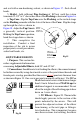
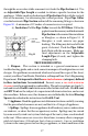
Fireplace. Push the gas fireplace towards the
firebox, and connect the Flex Pipe female cou-
pling to the appliance, or to the appropriate
connector as specified by the appliance manu-
facturer. If insufficient space is available be-
tween the top of the appliance, and the fireplace
opening, an access opening in the opposite side
of the masonry chimney may be necessary.
Position the gas appliance on it's final location,
again complying with the manufacturer's in-
structions in regards to location. Install any
shields or covers at this time.
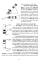
(f). Adjust Height. Go to the top of the chimney and pull the vent system
up to its desired height. In most cases, this will be 12 inches above the masonry
surface. Make a mark on the Pipe Section even with the top of the masonry
surface. If the top of the pipe is near a steep roof (more than 7/12 pitch) ,use
the height as stated in Table 2.
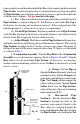
(g). Termination Assembly. Trim the Base Plate of the Termination
Assembly to cover the masonry opening. Refer to Figures 28 and 29. Slip the
Base down over the protruding Pipe Section. Use masonry anchors and non-
hardening sealant to secure the Base to the masonry.
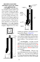
(h). Clamp. Pull the Pipe up through the Base to the mark, which you
previously made. Slip the Clamp down to the mark, and tighten it securely to the
Pipe. The Clamp will then support the entire venting system. Slip the Storm Collar
down over the Pipe Section, and seal the joint with a non-hardening sealant.
(i). Top. Install the Top, as shown in Figure 28. This concludes the
procedures for installing a gas fireplace in an existing masonry fireplace. Conduct
a final inspection of the system, and verify that the manufacturer's installation
instructions have been totally complied with.
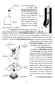
2. Gas Appliance Venting Into the Side Wall of a Masonry Chimney.
(a). Locate Appliance. Set the appliance in it's desired position, and
mark the center of the hole where the lateral Pipe Section is to pierce the
masonry chimney. Insure the manufacturer's requirements are complied with,
particularly in regards to distances from combustible surfaces. Refer to Figure
30.
(b). Hole in Masonry. Move the appliance aside, and break out the
masonry, forming a hole large enough for the Pipe Section to get through, and also
APPLY NON-
HARDENING
SEALANT AROUND
THESE SURFACES
MASONRY
ANCHORS
Fig 29
BASE OF GAS
RELINING
TERMINATION
ASSEMBLY
TRIMMED AND
SHAPED TO
FIT MASONRY AND
FLUE TILE