MODEL DVR (ROUND) TYPE-B GAS VENT INSTALLATION INSTRUCTIONS MH6357 Read through all of these instructions before beginning your installation. Failure to install as described in these instructions will void the manufacturer’s warranty and may have an effect on your homeowner’s insurance and UL listing status. Keep these instructions for future reference. REFERENCES (1) National Fuel Gas Code, also referred to as NFPA 54 and ANSI Z223.
II, III, or IV gas appliances. Type B Vent shall not be used to vent flue products from incinerators, combination gas/oil appliances, oil-fired, or wood-burning appliances. If there is a question about the use of Type B Vents, contact the appliance manufacturer or Simpson Dura-Vent's Engineering Department for further information. PLANNING 1. Appliances.
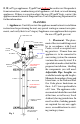
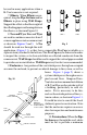
. Figures 1, 2, & 3 show examples of some typical residential installations. CEILING SUPPORT / FIRESTOP TOTAL VENT HEIGHT 90° ADJUSTABLE ELBOW B-VENT TEE B-VENT PIPE WATER HEATER CONNECTOR RISE FURNACE CONNECTOR RISE INCREASER 4. Clearance to Combustibles. A 1-inch clearance (air space) to combustible materials must be maintained, when using Simpson Dura-Vent Round BVent, regardless of the pipe diameter. WATER HEATER WITH DRAFT HOOD FAN ASSISTED FURNACE LATERAL 5. Combustion Air.
is within 8 feet. Vent pipe with 14" or larger diameter must terminate at least 2 feet higher than an adjacent wall or obstruction, if it is within 10 feet. 8. Connector Rise. Plan a minimum of one foot vertical connector rise coming out of each appliance.
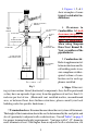
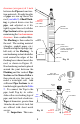
Table 1 PIPE SIZE STOCK NUMBER OF CEILING SUPPORT 3 INCH 1440 4 INCH 1441 5 INCH 1442 6 INCH 1443 7 INCH 1444 8 INCH 1445 10 INCH 1446 12 INCH 1447 EXISTING SHEET ROCK FRAMING MEMBERS REQUIRED FOR SUPPORT Fig 5 Firestop Supports are currently manufactured for FRAMED INSIDE pipe sizes of 3" through 12" DIMENSIONS (X & Y) FIG 4 only.
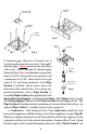
HANGER STRAPS CLAMP AND HARDWARE HANGER STRAPS CEILNG SUPPORT Fig 7 NAILS (4 REQ) CLAMP Fig 6 8" diameter pipe. However, if desired, use 1/ 4-inch long sheet metal screws for 3" through 8" diameter pipe. Never penetrate the inner liner B-VENT with screws. For 10" through 16" diameter pipe, PIPE SECTION Simpson Dura-Vent recommends using a minimum of (4) 3/8" sheet metal screws per joint, and a minimum of (6) 3/8" sheet metal screws per PIPE COLLAR joint for 18" and larger diameters.
be used in many applications when a B-Vent connector is not required. 7. Elbows. When Elbows are required, strap the Pipe Sections and/or Elbows in place using Wall Straps. Support the offset so that the weight of the offsetting pipe is not bearing down on the elbows, as shown in Figure 10. STEP 2 STEP 3 8. Tees and Wyes. Tees and Wyes are used to combine connectors from 2 or more appliances into a common vent as shown in Figures 2 and 3.
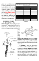
clearance (air space) of 1 inch between the Pipe and construction materials. Straight lengths of pipe are run up above the roof. (see table 2) A Roof Flashing is placed down over the pipe, and adjusted so it fits tightly against the roof, with the Pipe Section held in a position maintaining the 1 inch minimum clearance from combustibles. The Flashing is then nailed to the roof. The roofing material (shingles, asphalt paper, etc.) should overlap the top edge (uphill side) of the Flashing.
pletes the installation steps. Conduct a final inspection to insure that all joints are secure, the system is properly supported, and is mechanically sound. Especially verify that the one-inch clearance to combustibles requirement has been met, and that adequate combustion air will be furnished to the appliance. GAS VENT SYSTEMS USING VENT CAPS LISTED BY UNDERWRITER’S LABORATORIES MAY TERMINATE IN ACCORDANCE WITH THIS VENT TERMINATION TABLE ROOF PITCH MINIMUM HEIGHT FEET METERS FLAT TO 7/12 1 0.
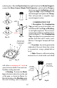
nail into place. Run the Pipe Sections through the hole in the Bucket Support, connect the Dura-Connect Single Wall Connector, and attach the Clamp so that it rests inside the Bucket, and will support the Pipe. Adjust the Pipe to the desired height and tighten the Clamp. This will provide a complete engineered support system. 1-1/2 TO 3 INCHES COMBINATION TOP 1. Description. The Combination Top, provides an easily installed, safe and efficient B-Vent Top and Flashing, as one lightweight unit.
and seal with a non-hardening sealant, as shown in Figure 17. Seal all nail heads. 5. Height. Add sufficient Pipe Sections of B-Vent until the system terminates 1-1/2" to 3" above the collar of the Flashing as shown in Figure 16. 6. Top Cone. Slip the Top Cone over the Flashing, so the vertical straps on the Flashing coincide with the slots at the base of the Cone. Slip the straps up through the slots as shown in SHEET Figure 18. Adjust the Top Cone to METAL SCREW 1/43/8" a generally vertical position.
MALE FEMALE 10° DISPLACEMENT Fig 21 does no longer have a 90° angle. 4. 45° Offsets with 90° Elbows. Figure 21 shows a 90° Adjustable Elbow being utilized to accomplish a 45° offset. This Elbow is completely adjustable from 0° to 90°. Please note that the centers of the upper sections tend to displace by a slight amount, as they are rotated. Again, screws (not longer than 1/4") may be used to secure the joint. Wall Straps should also be utilized to enhance the stability of the vent system.
RELINING MASONRY CHIMNEYS FOR USE WITH GAS APPLIANCES 1. Description. A masonry chimney should be relined with B-Vent when venting a Category I gas appliance, such as a gas fireplace insert or freestanding gas stove, or to improve the venting and reduce condensation of existing gas appliances which are currently venting into the masonry chimney.
DRAFT HOOD CONNECTOR Fig 26 in your measurements. (b) Pipe and Fitting Requirements. The bottom 5 foot section of vent will be Flex Pipe (used to get around the smoke shelf, and to connect to the appliance). The remainder will be rigid B-Vent Pipe Sections. For each pipe Fig 27 joint, subtract 1-1/2 inches. (c). Connector. Read the appliance manufacturer's instructions for connecting the Flex Pipe to the appliance. In most cases, a Draft Hood Connector will be required as shown in Figure 26.
BASE OF GAS Fireplace. Push the gas fireplace towards the MASONRY RELINING ANCHORS TERMINATION firebox, and connect the Flex Pipe female couASSEMBLY TRIMMED AND pling to the appliance, or to the appropriate SHAPED TO FIT MASONRY AND connector as specified by the appliance manuFLUE TILE facturer.
large enough to reach through and hold the Tee, while connecting the horizontal Pipe Section. An alternate procedure is to make the hole only large enough for the Pipe Section to pass through, and construct an access gate on the other side of the masonry chimney. Do not mortar to the pipe. . (c). Tee. A Tee is installed at the bottom end of the assembled vertical Pipe Sections, as shown in Figure 30. The Tee has a removable Tee Cap at the bottom, for cleaning and condensate removal.
through the access door while someone twist-locks the Pipe Section to it. Use an Adjustable Pipe Length as needed to obtain a specific location for the appliance. Make a mark on the horizontal Pipe Section flush with the vertical face of the masonry, for referencing the vertical position. Slip a Pipe Collar over the horizontal Pipe Section and install the remaining fittings as shown in Figure 30. A minimum of 12 inches of connector rise is required. (i). Insulation.
vent cap. 4. Blockage. Check the system for blockage by removing the cap, and looking down into the vent with a flashlight. Check for bird nests, debris, rodents, insects, or other obstructions. If nothing is found, inspect the entire system for physical damage. 5. Downdraft. Downdrafts are generally caused by the system's termination being too close to an adjacent wall, parapet, or other structure. If the cap is within eight feet of such an obstruction, it must also be at least two feet above it.
prevent rusting and corrosion on the exterior surfaces. MAINTENANCE 1. An annual inspection is required to maintain warranty of your Simpson Dura-Vent B-Vent system. You will need to inspect the Cap, Vent Pipe, Connector Pipe, and the connection to the appliance. 2. Verify that the sealant around the Flashing and Storm Collar is intact. Reseal as needed. Remove Cap. Hold Cap by the collar only, and unlock by twisting counterclockwise, and then pull up.
Simpson Dura-Vent offers the industry’s only twenty-five year warranty on Type B gas vent system and is UL listed. This warranty is in effect from the date of installation and includes all components and fittings. Simpson Dura-Vent warrants the following products: All Fuel Class A Chimney - Dura/Plus® and Dura-Chimney®; Close Clearance Connector Pipe - DVL®; Type B Gas Vent and Pellet Vent® Chimney for a period of twenty-five years from date of installation.