PolyPro Double-Wall Flex Gas Vent System for Category II & IV Gas-Burning Appliances ® PolyPro Flex Installation Instructions
A MAJOR CAUSE OF VENT RELATED FIRES IS FAILURE TO MAINTAIN REQUIRED CLEARANCES (AIR SPACES) TO COMBUSTIBLE MATERIALS. IT IS OF THE UTMOST IMPORTANCE THAT POLYPRO® BE INSTALLED ONLY IN ACCORDANCE WITH THESE INSTRUCTIONS. important Throughout this manual you will see special attention boxes intended to supplement the instructions and make special notice of potential hazards.
For the most up-to-date installation instructions, see www.duravent.com CONTENTS PolyPro Flex PolyPro Flex Gas Vent System Application . . . . . . . . . . . . . . . . . . . . . . . . . . . . . . . . . . . . . . . . . . . . . . . . . . . . . . . 4 minimum clearance to combustibles . . . . . . . . . . . . . . . . . . . . . . . . . . . . . 4 GENERAL INSTRUCTION NOTES . . . . . . . . . . . . . . . . . . . . . . . . . . . . . . . . . . . . .. . . . 4 installation of flex gasket . . . . . . . . . . . . . . .
APPLICATION / LISTING important For specific information on application, equivalent length of fittings, listings, etc., please reference M&G Duravent's installation instructions for rigid pipe (Document L273). The vent system must terminate in accordance with local code requirements and appropriate National Codes: In the US: NFPA 54 / ANSI Z223.1 National Fuel Gas Code or the International Fuel Gas Code. In Canada: CAN/CGA-B149.1 Natural Gas Installation Code or CAN/CGA-149.2 Propane Installation Code.
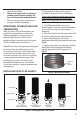
• • rather the top down. Always use soapy water to lubricate gaskets prior to joint assembly. Do not use Petroleum based lubricants! Plastic venting systems shall not pass through rated fire separations. additional instructions for termination M&G Duravent's PP Flex terminations are specifically designed for use with highefficiency appliances that are known to produce high volumes of fluid due to condensation of moisture within flue gases. DO NOT modify these terminations.
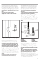
5. Close locking tabs on flex adapter so tabs seat in the flex pipe. Slight adjustment of pipe may be needed to ensure proper engagement. that is lined with a clay or concrete liner, check to see if a short portion of the tile is sticking out of the top of the chimney. If so, this short top portion must be broken off to permit the termination's flashing to sit down flush on the chimney's crown. It is best to do this prior to beginning the installation. 1.
to permit proper access. If this is the case, patch up the opening after the installation is completed using best practices. The slope of the rigid connecting flue pipe must have a minimum of 3° (equivalent 5cm/m) (5/8" per foot). 2. Fix the Flex Chimney Support (Fig.4) with 4 screws on the wall of the enclosure. 6. Install PP Flex liner into the enclosure. A second person is required to help feed the flexible liner into position (feeding either from the top or bottom of the enclosure).
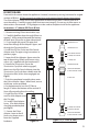
= 15. Install the Termination Pipe(see 1 , Fig.10). Assemble the storm collar portion of the Flex Chimney Flashing (see 2, Fig.10). 16. Connect the appliance to the flexible vent system with M&G DuraVent rigid PolyPro vent system. = = 3 = 1 2 A Figure 7, Mounting the Wall Plate 13. Fit the Support Bracket (see 1, Fig.8) over the liner and let it rest on the wall of the shaft. Mount the Gasket as detailed above (see Fig.1). Push the Flex Female Adapter on the liner and close the latching tabs.
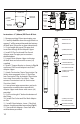
B VENT RELINE: From within the room where the appliance is located, remove any existing horizontal or angled sections of B Vent. PP Flex cannot be installed at an angle greater than 45 degrees from vertical. The B Vent Adapter-Lower will fit over the bottom of the existing B Vent's vertical stack at or near the ceiling. Carefully inspect the B Vent to ensure integrity. Ensure any visible screws or obstructions are removed.
b vent pipe mounting hardware b vent adapterlower flex male adapter c support bracket flex female adapter b vent adapterupper b vent pipe Figure 13 Figure 14 Instructions- 3" (80mm) PP Flex in B Vent 1. Remove existing B Vent termination cap 2. Carefully feed flex down through B Vent so approx 2' of flex extends beyond the bottom of the B Vent (Flex puller or rope aid optional) 3. Cut to length the top of Flex pipe and insert flex through B Vent Adapter- Upper 4.
Polypro WARRANTY M&G DuraVent, Inc. (“DuraVent”) provides this warranty for PolyPro® for ten years. Subject to the limitations set forth below, DuraVent warrants that its products will be free from defects in material or manufacturing, if properly installed, maintained and used. DuraVent products are fully warranted if installed only by a professional installer. This Warranty is transferable from the original homeowner to the buyer of the home within the warranted ten years.