FasNSeal Double-Wall vent for Category II, III, and IV appliances FasNSeal W2 Installation Instructions
A MAJOR CAUSE OF VENT RELATED FIRES IS FAILURE TO MAINTAIN REQUIRED CLEARANCES (AIR SPACES) TO COMBUSTIBLE MATERIALS. IT IS OF THE UTMOST IMPORTANCE THAT FasNSeal W2 BE INSTALLED ONLY IN ACCORDANCE WITH THESE INSTRUCTIONS. IMPORTANT: Read through all of these instructions before beginning your installation.
CONTENTS FasNSeal W2 FASNSEAL DOUBLE-WALL VENT FOR CATEGORY II, III, AND IV APPLIANCES Introduction; General Requirements . . . . . . . . . . . . . . . . . . . . . . . . . . . . . . . . 4 Vent Size and Length; Adjustable Vent. . . . . . . . . . . . . . . . . . . . . . . . . . . . . . . 5 Joint Connections; Appliance Connection. . . . . . . . . . . . . . . . . . . . . . . . . . . . 6 Condensate Drains; Horizontal Through-The-Wall Installation.. . . . . . . . . . .
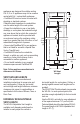
introduction FasNSeal W2, manufactured by DuraVent, is a Double-Wall special stainless steel vent system for gas fired appliances listed as Category II, III, and IV or in Canada, Type BH Gas Venting Systems as noted in ULC-636, with a rated operating temperature of 480 Degrees F (249 Degrees C), and a rated positive pressure of 6” Water Column. FasNSeal W2 must be installed by an experienced professional familiar with the operation and maintenance of heating appliances and venting.
appliances are designed for multiple venting. Cat. II, III or IV appliances may not be common vented with Cat. I, natural draft appliances. • FasNSeal W2 must not come in contact with plumbing or electrical systems. • Maintain rated clearances to combustibles over the entire length of the vent system.
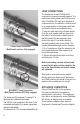
JOINT CONNECTIONS Correct Joint Connection. Male/Female sections fully engaged. The female end of each FasNSeal W2 component incorporates a sealing gasket. The mechanical locking band is built into the outer tube of FasNSeal W2 male end. Examine all components prior to installation. Gaskets must be in proper position or flue gases could leak and result in carbon monoxide poisoning. 1. Insert the male end into the female section.
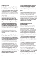
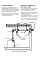
CONDENSATE DRAINS If instructions or local regulations call for a condensate drain, use a FasNSeal W2 Drain Fitting and a 5/8” ID plastic tube of appropriate size to connect the Tee into the sanitary sewer drain. Always create a siphon loop in the plastic tube. Follow all local and national codes for draining acidic effluent. Do not use copper as a drain as it may corrode. HORIZONTAL, THROUGH THE WALL INSTALLATION • When venting through a sidewall, terminate the system not less than 12” (.
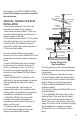
Inside Building Surface Part B 1.0” 1.5” To Appliance Outside Building Surface Part A To Termination 4.3” - 8.6” 2” x 6” Stud (Combustibles) Wall Thimble Installation opening, gas utility meter, service regulator or the like. It also shall terminate at least 3’ (.9m) above any forced air inlet within 10’ (3.1m) and shall terminate at least 4’ (1.2m) below, 4’ horizontally from or 1’ (.
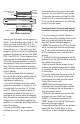
for procedure. (see JOINT CONNECTIONS) Do not drill through or penetrate any part of the vent system. RAINCAP STORM COLLAR ADJUSTABLE FLASHING VERTICAL, THROUGH THE roof INSTALLATION • Terminate the system 6’ (1.8m) from the combustion air intake of any appliance. • Terminate the system at least 3’ (.9m) from any other building opening, gas utility meter, service regulator or the like. • Terminate the system at least 2’ (.61m) above the roofline and any wall or vertical structure closer than 8’ (2.4m).
.To inspect the vent system, open the locking band and remove the Rain Cap. FasNSeal EXTERIOR WALL BRACKETS Pre-Installation 1. Wall Brackets must be securely fastened to a solid member of the building using appropriate fasteners - Tapcon screws for solid masonry, wood screws for wood framing or sheet metal screws for structural steel. 2.
FasNSeal Double-Wall Clearances to Combustibles Rated Operating Temperatures Minimum Clearance Enclosed Clearance Unenclosed Horizontal Vertical Horizontal Vertical 3" & 4" 300°F 400°F 480°F 3" 6" 6" 1" 1" 4" 1" 3" 3" 1" 1" 1" 5" - 24" 300°F 400°F 480°F 3" 6" 6" 1" 1" 6" 1" 3" 3" 1" 1" 3" Rated Operating Temperature of 300°F = Max Flue Gas Temperature of 375°F Rated Operating Temperature of 480°F = Max Flue Gas Temperature of 550°F 11
M&G DuraVent limited lifetime Warranty M&G DuraVent, Inc. (“DuraVent”) provides this limited lifetime warranty for all of its products with the exception of Ventinox® (lifetime), and PolyPro® (ten years). Subject to the limitations set forth below, DuraVent warrants that its products will be free from defects in material or manufacturing, if properly installed, maintained and used. DuraVent products are fully warranted if installed only by a professional installer.