
Installation Guide


7
Cap can be swiveled to be directed away
from nearby objects (fence, plants, etc.),
but must still be pointing in a generally
downward direction. Important: Horizontal
Caps must be pointed in a generally
downward direction to insure rain and snow
do not enter the cap, and cause potential
damage to the appliance. Either vent Cap
should be at least 6” from the wall.
C. Follow the appropriate code for proper
distance of exit terminal from windows and
openings-
NFPA 211 (2010 ed.) Section 10.4 Termination:
10.4.5 (1) The exit terminal of a mechanical
draft system other than a gas-, oil- or
pellet-red direct vent appliance (sealed
combustion) shall be located in accordance
with the following:
(a) Not less than 3 ft (.92m) above any forced
air inlet located within 10 ft. (3m).
(b) Not less than 4 ft. (1.2m) below, 4 ft. (1.2m)
horizontally from, or 1 ft. (305mm) above
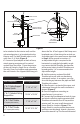
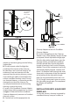
Figure 2
Figure 3
12 INCHES
MINIMUM
APPLY HIGH
TEMPERATURE
SEALANT COMPLETELY
AROUND TOP EDGE OF
STORM COLLAR
SHINGLES OVERLAP ON
TOP EDGE OF FLASHING
TEE WITH
CLEANOUT
ADAPTER
CEILING
SUPPORT/
FIRESTOP
SPACER
ATTIC
INSULATION
SHIELD
PIPE
ADAPTER
12” MIN
any door, window or gravity air inlet into any
building.
(c) Not less than 2 ft. (0.61m) from an
adjacent building and not less than 7 ft
(2.1m) above grade when located adjacent to
public walkways.
6. If it is desired to attach to an existing 6”,
7” or 8” DuraTech, DuraPlus or DuraChimney
chimney, either roof supported, or ceiling
supported: (Figure 7).
A. Remove any existing connector pipe,
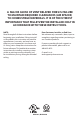
WARNING
WARNING: Do not install any
combustible insulation or other
non-approved material inside the
Wall Thimble. Doing so can create
a re hazard. If desired, reference
approved non-combustible insulation
requirements detailed earlier in this
text.