® Flexible aluminum relining system for relining masonry chimneys for natural gas or liquid propane category I, draft hood equipped appliances, and appliances tested and listed to use Type B gas vent.
A MAJOR CAUSE OF VENT RELATED FIRES IS FAILURE TO MAINTAIN REQUIRED CLEARANCES (AIR SPACES) TO COMBUSTIBLE MATERIALS. IT IS OF THE UTMOST IMPORTANCE THAT DuraFlex AL BE INSTALLED ONLY IN ACCORDANCE WITH THESE INSTRUCTIONS. NOTE: Read through all of these instructions before beginning your installation. Failure to install as described in this instruction will void the manufacturer’s warranty, and may have an effect on your homeowner’s insurance and UL listing status.
For the most up-to-date installation instructions, see www.duravent.com CONTENTS Application, Warning, Important, Installation Precautions, DuraFlex AL Flexible aluminum relining system Sizing Requirements. . . . . . . . . . . . . . . . . . . . . . . . . . . . . . . . . . . . . . . . . . . . . . . . . . . 4 Prior to Installation, Chimney Liner Selection . . . . . . . . . . . . . . . . . . . . . . . . 5 Flexible Liner Installation. . . . . . . . . . . . . . . . . . . . . . . . . . . . . . . . . . .
APPLICATION The DuraFlex AL Chimney Relining System is UL listed for relining masonry chimneys which are intended to be used for venting gas appliances and decorative gas fireplaces. These instructions cover installation from the appliance vent connector through the wall of the masonry chimney, or through the damper, up to the termination cap.
For complete sizing instructions, refer to the National Fuel Gas Code , the International Fuel Gas Code, or the DuraVent Sizing Handbook. Failure to properly size the venting system may result in draft hood spillage, back pressure, and corrosive condensation in the relining system. As an alternate method, for draft hood-equipped appliances and decorative gas fireplaces only, the venting system may be sized to the outlet of the appliance.
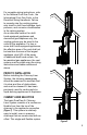
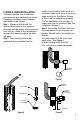
optional high wind cap Figure 3 optional high wind cap Figure 4 6 is intended for warm interior masonry chimneys, enclosed within the building on all four sides, and thus exposed to cold outdoor temperatures only above the roof line. In cold climates, it is preferable to switch to double-wall, air insulated Type B Gas Vent near the top exposed portion of the chimney (Figure 2).
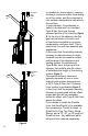
FLEXIBLE LINER INSTALLATION The basic flexible liner installation procedure for gas appliances such as Category I furnaces, water heaters, and boilers is as follows: Step 1. Measure and record the interior dimensions of the masonry chimney and the height of the chimney from the top, down to the penetration through the masonry where the liner will pass. Step 2.
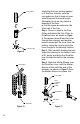
flex liner tee body flex puller Figure 9 flex liner stretching the liner as they backup. c. At the liner extends, note the corrugation so that it does not overextend beyond its normal length. Attempting to do so may result in damage to the liner. d. Use the same procedure for the other half of the liner. Step 4. Secure a rope to the Flex Puller and attach the Flex Puller to DuraFlex Liner, as shown in Figure 6.
space between the sleeve/pipe and the masonry may be filled with grout. Step 7. The Flex Liner should extend at least 2 inches beyond the flange on the Mortar Sleeve. If Type B Gas Vent or the DuraConnect Flexible Vent Connector is to be used between the appliance and the chimney liner, slide the Flex Coupling or B-Vent Female Adaptor over the Flex Pipe, and secure with either a nut & bolt or sheet metal screw, as appropriate. Refer to Figure 8.
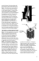
screws. Slide the Mortar Sleeve over the connector and branch, and fill in around the Mortar Sleeve with grout, keeping the Tee centered in the masonry chimney, and the flange of the Mortar Sleeve even with the wall of the chimney. Step 5. Complete the Vent Connector attachment to the gas appliance.
TERMINATIONS Step 1. When terminating your Flex installation, ensure the Flex protrudes 4-5 inches over the top of the masonry chimney, as shown in Figure 13. Trim the base of the Top Plate to fit on the masonry chimney as needed. Step 2. Slide the Top Plate over the Flex and seal the Top Plate to the masonry chimney using a bead of non-hardening sealant around the top of the chimney. Refer to Figure 14. Step 3.
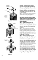
optional high windcap standard cap support Figure 18 flex liner flex coupling up to 50 feet of Flex or B-Vent Liner. Refer to Figure 17. Step 4. Seal the Storm Collar to the Top Plate and twist-lock the B-Vent top to the B-Vent pipe. As an alternative to the standard cap, you may want to install a B-Vent High-Wind Top in areas where excess wind may be a concern (Figures 17 & 18). Step 5.
purchased in various lengths. Two lengths of Flex may be connected using the Flex Coupling (Figure 19). Connect the DuraFlex AL sections to either end of the Flex Coupling using (4) sheet metal screws.
Important Notice on stretching Aluminum flex: Follow these instructions carefully to prevent injury and damage to liner. Correct Stretching Technique For DuraFlex Aluminum Chimney Liner Two people are needed to stretch the aluminum flex. Stretch half the length of the liner at a time following this procedure: • Start by facing each other at the mid-point in the liner. • Hold the liner firmly in hands. One person walk backwards, stretching portions of the liner as he or she is backing-up.
M&G DuraVent limited lifetime Warranty M&G DuraVent, Inc. (“DuraVent”) provides this limited lifetime warranty for all of its products with the exception of Ventinox® (lifetime), and PolyPro® (ten years). Subject to the limitations set forth below, DuraVent warrants that its products will be free from defects in material or manufacturing, if properly installed, maintained and used. DuraVent products are fully warranted if installed only by a professional installer.