
Installation Guide

www.dural.com
02/2015
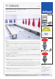
Floor Drain with System Seal
TI-DRAIN 2/2
HANDLING:
Prior to installation, rst connect the outlet drain from Module 3 to the sealing component from
Module 2. The outlet drain and seal are securely connected when they‘re tightly fasten against
each. For installation near a wall, the overlapping WP lm or glass-bre fabric can be folded and
applied to the vertical surface.
TI-DRAIN must be aligned to the height of the drainage point for the building, taking into account
a necessary oor surface slope of around 1-2%, and cemented to the substrate using screed mor-
tar or adhesive. When doing so, make sure that the drain casing is level horizontally.
If quick-curing cement is used, after a short hardening period, the drain pipe for the outlet drain
can be connected to the main drainage pipe for the building using a pusht socket. The drainage
slope between the TI-DRAIN drain and the main drainage pipe for the building should be at least
0.5%. Once assembly work is complete, check that the connections are watertight and that the
drain functions correctly. To prevent blockages of the drainage system due to dirt and cement, x
the smaller of the two red protective covers.
If necessary, appropriate soundproong measures must be taken in the oor drain/drain pipe area
to prevent acoustic bridges.
After completing the installation work, produce a water-tight connection to Module 2 as part of
production of the composite seal. If you are using the WP seal, bond the yellow WP membrane
to the entire screed surface using exible mortar (C2) using a 4 mm serrated trowel, making
sure that no air bubbles are formed. The composite seal which will then be produced, e.g. using
DURABASE WP, is secured to the WP seal by overlapping approx. 8-10 cm, resulting in a waterproof
seal (e.g. using Sopro-Turbo 2K waterproong ller). If a spreadable sealant is used, the mesh is
embedded between the rst and second sealing layer, making sure that the surface is at. Alter-
natively, the same sealant installation can also be used with the WP seal.
As part of subsequent tiling work, rst remove the protective cover again and then screw Module
1 onto Module 2. To do this, screw the threaded adapter from Module 1 into the ange ring of
Module 2. Then screw the plastic holder onto the threaded adapter (both Module 1) and align at
the height of the upper edge of the tiled surface. Afx the stainless steel frame onto the plastic
holder and then t the stainless steel cover grate. To align the height of the plastic holder, a 7-17
mm material thickness for the stainless steel frame should also be taken into account to ensure
that the tiled surface produces a ush surface nish with the stainless steel frame. Before atta-
ching the stainless steel cover grate, the siphon (anti-odour seal) must be inserted to check that
the drain bowl of the anti-odour siphon functions correctly.
The connecting joint between the stainless steel frame and the surrounding tiled surface must be
produced at a width of approx. 5 mm and sealed using an elastic joint material (e.g. MS polymer
rubber).
CLEANING AND CARE:
TI-DRAIN does not normally require any special care, since the majority of components are located
in the oor structure. Only the stainless steel grate should be cleaned during normal maintenance
cleaning using a suitable commercially available detergent. The use of detergents containing hy-
drochloric or hydrouoric acid should be avoided.
To guarantee that the TI-DRAIN board retains its consistent drainage capacity over the long term,
the oor drain unit should be inspected and cleaned at regular intervals.
EN