
Installation Guide

polishedpro | 5.2mm Rigid Core
DuraDecor | P: (855) 700 - 5666 | customercare@duradecor.com | duradecor.com | revised on 06.23.23 | Page 7
previous row, and follow the "Side Joints" detail below.
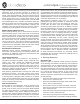
Side Joints (Angle)
Starting at the left corner, typically with a cut piece, insert
the side without an extended locking mechanism (tongue)
into the previous row at a ~25° angle. Make sure it is
properly seated and slides freely, then slide the piece into
position. The end joint must either be ush with the wedge
spacer (rst piece) or be closely aligned with the end of the
previous piece. Lay the piece at and complete the end joint
as detailed below.
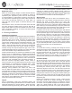
End-Joints (Drop-Lock or Fold-Down)
Before locking end joints into place, check the alignment
at the joint and adjust as necessary. To engage the locking
mechanism, lightly tap along the raised piece using a 1-lb. (~
16-oz.) soft faced dead blow hammer (preferred) or rubber
mallet. Keep the striking head at with the oor covering
and tap until the joint is completely ush. If the end joint is
not properly aligned, it may break - pieces with damaged
or broken locking mechanisms must be removed per the
process below. When replacing damaged pieces, adjust the
straightness of the row and/or the alignment of the joint
prior to engaging end joints to prevent further damage.
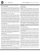
Flooring Removal
If you need to replace a piece or disengage the end joints
for any reason, rst unlock the side joints of the entire
row by raising the outside edge of the row by ~25°, then
disconnect the row from the installation. Once the row
is removed, ensure that all pieces are lying at and are
properly engaged, then slide each piece apart. If pieces do
not slide easily, the locking mechanism may not be fully
engaged – simply tap the piece with a dead blow hammer
or rubber mallet to fully engage and slide apart. Do not
separate pieces by angling them or pulling them upward, as
this will break the locking mechanism.
Additional Tips
Do not hit any part of the locking mechanism directly with
any hammer, tapping block or pull bar unless it is the last
row - doing so will damage the locking mechanism and
may result in peaking, gapping and joint separation. If you
need to tighten gaps in the installation, use a ~6-in. piece of
scrap oor covering, seated in the locking mechanism, and
lightly tap to close any joints.
If you need to install small pieces that are < 3-in. in
length or width, place a thin bead of Liquid super glue on
the previously installed locking mechanism just before
installing. This will ensure the joints remain locked together
during use. Do not get the adhesive on the surface, be
prepared and if required, immediately remove adhesive
using isopropyl alcohol with a clean white cloth - super glue
coverage should be ~30 feet per oz.
After the rst ve or six rows are completed, turn the
installation process around so that you are working on top
of the installed material. This will allow the side joints to be
pulled together rather than pushed, which will make the
installation easier.
Post-Installation
Visually inspect the installation to ensure that the
appearance is uniform and straight, that the locking
mechanisms are fully engaged, that all seams are tight and
correctly staggered/spaced, and that the expansion gap is
the correct width. Trim o any excess plastic sheeting as
necessary. Fill any perimeter gaps that will not be covered
by an accessory with a 100% silicone, color-coordinated
caulk. When spot cleaning, do not apply abrasive or
solvent-based cleaners directly to the surface of the oor
covering. When covering perimeter gaps with an accessory
(wall base, molding, thresholds, t-molding, etc.), ensure the
accessory overlaps the ooring material by at least 1/8-
in.. All accessories must be glued or anchored directly to
the substrate or vertical surface. When required, protect
newly installed ooring with construction grade paper
or protective boards, such as Masonite, Ram Board or
plywood, to prevent damage from other trades. Take
photographs and have any required documentation signed
and led following completion. Save three or more extra
pieces of material in the original packaging as attic stock
for the lifetime of the oor. In the unlikely event of a
product issue, attic stock can play a crucial role in product
identication, color matching, product claim verication
and possible repairs.
4. Flooring Protection
Do not slide or drag heavy objects across the oor. When
moving appliances, heavy furniture or equipment, protect
the ooring with appropriate, hard surface furniture sliders
or 1/2-in. plywood.
All furniture casters or glides must be intended for resilient
ooring and made of a soft material, such as a felt, silicone
or a poly-based material. Casters and glides must have
a at contact point that is at least 1 -sq. in. or 1.125-in. in
diameter to limit indentation and ooring or nish damage.
All rolling seating in desk areas must have chairs that use
soft, W-Type polyurethane wheels and a polycarbonate
resilient ooring chair pad installed over the nished oor
to protect it. Do not use nylon/hard plastic wheels, glides
or casters.
All xed furniture legs or corners must have permanent
oor protectors installed on all contact points to reduce
indentation, wear, scratching and other ooring or nish
damage. Floor protectors must be intended for resilient
ooring and made of a soft material (such as a felt, silicone
or a poly-based material). Floor protectors must have a at
contact point of at least 1 -sq. in. or 1.125-in. diameter and
must cover the entire bottom surface of the furniture leg.
Do not use nylon/hard plastic oor protectors or furniture
feet.
Ensure all furniture castors and chair legs are clean and