WPSB SERIES II Models WPSB-3D WPSB-3DP WPSB-4D WPSB-4DP WPSB-5D WPSB-5DP WPSB-6D WPSB-6DP WPSB-7D WPSB-7DP WPSB-8D WPSB-8DP WPSB-9D WPSB-9DP GAS-FIRED HOT WATER BOILERS INSTALLATION, OPERATION & MAINTENANCE MANUAL Tested For 50 psi. ASME Working Pressure Manufactured by: ECR International, Inc. An ISO 9001-2008 Certified Company 2201 Dwyer Avenue, Utica NY 13501 web site: www.ecrinternational.com P/N 240009047, Rev.
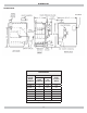
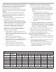
DIMENSIONS DIMENSIONS CONTROL Dimensions DIMENSIONS (INCH.) BOILER MODEL NUMBER FLUE DIAMETER “A” WIDTH Boiler Volume Gallon WPSB-3 5 11¼ 6.3 WPSB-4 6 14½ 8.1 WPSB-5 6 17¾ 9.9 WPSB-6 7 21 11.7 WPSB-7 7 24¼ 13.5 WPSB-8 7 27½ 15.3 WPSB-9 7 30¾ 17.2 Add 5½” to height for vent Damper.
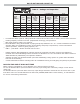
BOILER RATINGS AND CAPACITIES Table 1 - Ratings and Capacities † NATURAL GAS BOILER MODEL NUMBER (1) † (1) (2) (3) - - Input (3) Mbh Heating Capacity (3) Mbh † PROPANE GAS (2) NET AHRI RATING Water, (3) 63 INPUT (3) Mbh Mbh 55 70 HEATING CAPACITY (3) MBH 59 AFUE (2) NET AHRI RATING (3) Mbh INTERMITTENT IGNITION WITH VENT DAMPER WPSB-3 75 51 84.0 WPSB-4 112.5 94 82 105 WPSB-5 150 126 110 140 88 77 84.0 118 103 84.1 WPSB-6 187.5 157 137 175 147 128 84.
TABLE OF CONTENTS KEEP THIS MANUAL NEAR BOILER RETAIN FOR FUTURE REFERENCE Locating The Boiler .............................................. 5 Ventilation & Combustion Air ................................. 6 Connecting Supply And Return Piping ..................... 7 IMPORTANT: Read the following instructions COMPLETELY before installing!! Chimney And Vent Pipe Connection ...................... 11 Vent Damper Operation ...................................... 13 Gas Supply Piping .........................
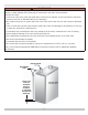
LOCATING THE BOILER ! WARNING ! WARNING Improper installation, adjustment, alteration, service or maintenance could result in death or serious injury. Fire hazard. Do not install boiler on combustible flooring or carpeting. Failure to follow these instructions could result in death or serious injury. 1. Installation must conform to requirements of authority 2. 3. 4. 5. 6. 7. 8. 9. 10. having jurisdiction or, in absence of such requirements, to the National Fuel Gas Code, ANSI Z223.1/NFPA 54.
VENTILATION & COMBUSTION AIR Provide combustion air and ventilation air in accordance with the section “Air for Combustion and Ventilation,” of the National Fuel Gas Code, ANSI Z223.1 / NFPA 54, or applicable provisions of local building codes. • All Outdoor Air. Provide permanent opening(s) communicating directly or by ducts with outdoors. A. Two Permanent Opening Method. Provide opening commencing within 12 inches of top and second opening commencing within 12 inches of bottom of enclosure.
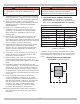
CONNECTING SUPPLY AND RETURN PIPING ! WARNING Burn or Scald Hazard. Discharge line shall be installed to relief valve outlet connection to avoid burns, scalding, or water damage due to discharge of steam and/or hot water during operation. Discharge line shall: • Connect to relief valve outlet and piped down to safe point of disposal. Check local codes for maximum distance from floor or allowable safe point of discharge.
CONNECTING SUPPLY AND RETURN PIPING Verify clean water supply is available to water inlet valve. Install sand strainer when water supply is from a well or pump. ! WARNING Burn and scald hazard. Safety relief valve could discharge steam or hot water during operation. Install discharge piping per these instructions. Install hot water boiler above radiation level or as required by Authority having jurisdiction install low water cutoff device at time of installation.
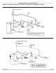
CONNECTING SUPPLY AND RETURN PIPING Figure 3- Typical Hot Water Piping Figure 4 - Chilled Water Piping 9
CONNECTING SUPPLY AND RETURN PIPING BYPASS PIPING REQUIRED FOR HIGH MASS (LARGE WATER CONTENT) SYSTEMS Figure 5 - Bypass Piping - Circulator On Supply Figure 6 - Bypass Piping - Circulator On Return 10
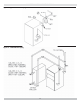
CHIMNEY AND VENT PIPE CONNECTION Boilers connecting to gas vents or chimneys, vent installations shall be in accordance with “Venting of Equipment”, of the National Fuel Gas Code, ANSI Z223.1/NFPA 54, or applicable provisions of local building codes. Connecting The Vent Damper And Vent Connector Refer to Dimensions, page 2 for size and location of vent (flue opening). NOTICE Check Your Chimney It must be clean, right size, properly constructed and in good condition.
CHIMNEY AND VENT PIPE CONNECTION Removing Existing Boiler From Common Venting System When an existing boiler is removed from common venting system, common venting system is likely to be too large for proper venting of appliances remaining connected to it. At time of removal of existing boiler, following steps shall be followed with each appliance remaining connected to the common venting system placed in operation, while other appliances remaining connected to common venting system are not in operation. 1.
VENT DAMPER OPERATION Figure 7 Figure 8 For safe, efficient operation, vent damper and all flue product carrying areas of appliance must be checked annually, with particular attention given to deterioration from corrosion or other sources. If you see corrosion or other deterioration, contact your heating contractor for repairs. Check vent damper operation as follows: • When boiler is off, check vent damper positions indicator points to closed position. See Figure 9.
GAS SUPPLY PIPING • Pressure test at 1/2 psig (3.5 kPa) or less. Isolate boiler from gas supply system by closing manual gas shutoff valve. • Locate leakage using gas detector, noncorrosive detection fluid, or other leak detection method acceptable to authority having jurisdiction. Do not use matches, candles, open flames, or other methods providing ignition source. • Correct leaks immediately and retest. ! CAUTION WHAT TO DO IF YOU SMELL GAS • Do not try to light any appliance.
ELECTRICAL WIRING ! WARNING Electrical shock hazard. Turn OFF electrical power supply at service panel before making electrical connections. Failure to do so could result in death or serious injury. VENT DAMPER WIRING Boiler is equipped with factory wired harness with 4 pin molex plug, that plugs into 4 pin molex receptacle inside vent damper operator. Vent damper must be connected for boiler to operate.
WIRING DIAGRAMS Figure 11 - Electronic Ignition Control ! WARNING Modification, substitution or elimination of factory equipped, supplied or specified components may result in personal injury or loss of life.
STARTING YOUR BOILER FILLING SYSTEM WITH WATER • Close air vents on all radiation units. Open valves to these units. NOTICE Never run water in a hot empty boiler. • Verify boiler and expansion tank drain valves are closed. • Close drain fitting on air bleed screw. • Open valve in line from boiler to expansion tank. Open water inlet to your boiler and leave it open. Start with lowest radiation unit. Open air vent on this unit. When all air has escaped and water starts to flow from vent, close it.
LIGHTING INSTRUCTIONS ! WARNING If you do not follow these instructions exactly, a fire or explosion may result causing property damage, personal injury or loss of life. F. Remove front panel. G. Rotate the gas control knob clockwise Figure 12 - Automatic Gas Valve LIGHTING PROCEDURE FOR BOILER WITH INTERMITTENT PILOT SYSTEM For Your Safety, Read Before Operating!! A. This appliance is equipped with an ignition device which automatically lights the pilot. Do not try to light appliance by hand.
OPERATING YOUR BOILER AUTOMATIC GAS VALVE Automatic Gas Valve opens or closes according to heat requirements of thermostat and temperature limit control. It closes if pilot goes out. Each individual control must be operating correctly before any gas can pass to burners. Any one control can hold gas supply from burner regardless of demand of any other control. Figure 13 - Pilot Flame SAFETY PILOT Safety Pilot prevents flow of gas to burner if pilot goes out, or will not ignite.
OPERATING YOUR BOILER CHECK THERMOSTAT OPERATION A. When set above temperature indicated on thermostat, boiler should ignite. B. Verify thermostat turns boiler off when room temperature reaches selected setting and starts boiler operating when room temperature falls a few degrees. C. After setting limit control to limit setting, check to see if it shuts off gas supply to burners. Turn your thermostat up to call for heat and let boiler run until temperature of water reaches limit setting.
OPERATING THE BOILER - SYSTEM START-UP 1 HI TEMP illuminates when boiler water temperature reaches high limit setting. Remains lit until water temperature falls 10°. Prevents burner operation while this LED is on. 2 LWCO Active Indicates low water cut-off (LWCO) function of limit control is active. When control is installed with a well, LED is on at all times when control is powered.
OPERATING THE BOILER - SYSTEM START-UP Table 1 - Troubleshooting Burner Will Not Fire No or Insufficient Domestic Hot Water House will not get or stay warm If installed with indirect water heater, insure end switch in relay box controlling indirect water heater is properly connected to cable 2 (see wiring diagram). This insures domestic water calls are prioritized. If cable 2 is not used, turn Economy Feature OFF. 1. Check for air bound radiators. 2.
SERVICE HINTS EQUIPMENT AND OPTIONAL ACCESSORIES - WHAT THEY DO You may avoid inconvenience and service calls by checking these points before you call for service. ! CAUTION WHAT TO DO IF YOU SMELL GAS • Do not try to light any appliance. • Do not touch any electrical switch; do not use any phone in your building. • Immediately call your gas supplier from a neighbor’s phone. Follow the gas supplier’s instructions. • If you cannot reach your gas supplier, call the fire department.
MAINTAINING YOUR BOILER BURNERS Beginning of heating season visually check pilot end main burner flames. See page 19 SAFETY RELIEF VALVE Test safety relief valve for proper operation. Refer to valve manufacturer’s instructions packaged with relief valve. Call Technical Support if manufacturer’s instruction are not located. CLEANING YOUR BOILER AND BURNERS Flue passages between sections should be examined yearly and cleaned if necessary. To clean: • Remove burners, pilot, and vent pipe.
EQUIPMENT AND OPTIONAL ACCESSORIES ! WARNING Burn and scald hazard. Safety relief valve could discharge steam or hot water during operation. Install discharge piping per these instructions. SAFETY RELIEF VALVE Safety relief valve is required on your boiler. Water expands as it is heated. If there is no place for water to expand into, water pressure will build up inside boiler and system. Should this happen, safety relief valve will automatically open at predetermined pressure.
EQUIPMENT AND OPTIONAL ACCESSORIES ROLLOUT SWITCH (FLAME ROLLOUT SAFETY SHUTOFF) Rollout switch is temperature-sensitive fuse link device. Located on boiler base just outside fire box. In event of heat exchanger flueway blockage causing flame to roll out of fire box, fuse does not change in appearance when blown. If rollout switch blows, it must be replaced with exact replacement. Check heat exchanger flueways for blockage when restoring system to operating condition.
NOTES
DUNKIRK BOILERS 2201 Dwyer Avenue, Utica NY 13501 web site: www.ecrinternational.