
Owner's manual


12
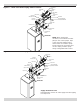
Condensate Drain Requirements
Pitch condensate drain line down to oor drain at
minimum of ¼” per foot (21mm/m). External condensate
pump (not furnished) may be used if oor drain is not
available. Condensate pump must be designed for ue gas
condensate application.
Condensate trap is proved with boiler.
1.
Build condensate trap in the eld. See Figure 7.
2.
Wood frame or blocks may be used to raise boiler
to maintain drain pitch or to be above external
condensate pump reservoir.
3.
115 volt AC receptacle provided on service switch
junction box which is located at boiler right side,
to provide power for external condensate pump (if
needed).
Condensate Drain Piping
• Condensate trap is to be eld installed as shown in
Figure 7.
• Provided are ½” PVC ttings for condensate drain trap
(assembled in eld).
• The ½” diameter schedule 40 PVC condensate drain
piping and pipe ttings must conform to ANSI standards
and ASTM D1785 or D2846.
• Schedule 40 PVC cement and primer must conform
to ASTM D2564 or F493. In Canada, use CSA or ULC
certied schedule 40 PVC drain pipe and cement.
• Condensate pump with reservoir (not furnished) may
be used to remove condensate to drain line (sanitary
line) above boiler if oor drain is not available or is
inaccessible
Filling Condensate Trap With Water
Manually ll condensate trap at initial start up with water
Following steps are required to ll condensate trap for
start up. Steps are only required at initial start up or if
maintenance requires draining of condensate trap:
1.
Pour about 1 cup of cold tap water into condensate trap
vent.
2.
Excess water will go through condensate drain line.
Verify proper operation of drain line (and external
condensate pump if used).
Chilled Water Piping
Install boiler used in connection with refrigeration system,
so chiller medium is piped in parallel with boiler with
appropriate valves to prevent chilled medium from entering
boiler.
Boiler piping system of hot water boiler connected to
heating coils located in air handling units where they may
be exposed to refrigerated air circulation must be equipped
with ow control valves or other automatic means to
prevent gravity circulation of boiler water during cooling
cycle.
4 - NEAR BOILER PIPING
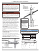
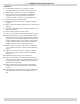
Figure 8 - Condensate Trap and Vent
To Exhaust Vent
(2” CPVC)
½” Adapter
Male NPT x Socket
Weld PVC Piping
1 3/8” Long
To Boiler Flue Outlet (2” CPVC)
2” Male x 2” NPT Male PVC Bushing
1/2” PVC Elbow
1/2” PVC Piping 3 3/4” Long
1/2” PVC Elbow
1/2” PVC Piping 2” Long
1/2” PVC Piping 3 3/4” Long
1/2” PVC Tee
To Condensate Drain (Field Supplied)
2” NPT Male PVC Bushing
1/2” PVC Piping 12” Long