PLYMOUTH STEAM SERIES 2 GAS-FIRED STEAM BOILERS INSTALLATION, OPERATION & MAINTENANCE MANUAL MODEL PVSB Continuous Pilot MODEL PSB Electronic Intermittent Ignition H ECR International, Inc. An ISO 9001-2008 Certified Company 2201 Dwyer Avenue, Utica NY 13504-4729 www.ecrinternational.com P/N# 14683003, Rev.
TABLE OF CONTENTS Safety Symbols .............................................................................................................. 3 Boiler Ratings And Capacities ........................................................................................... 4 Before You Start ............................................................................................................. 5 Locating The Boiler .............................................................................................
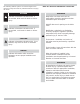
SAFETY SYMBOLS The following defined symbols are used throughout this manual to notify the reader of potential hazards of varying risk levels. READ ALL INSTRUCTIONS BEFORE INSTALLING. WARNING DANGER ! Keep boiler area clear and free from combustible materials, gasoline and other flammable vapors and liquids. Indicates a hazardous situation which, if not avoided, WILL result in death or serious injury. DO NOT obstruct air openings to the boiler room.
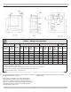
BOILER RATINGS AND CAPACITIES Figure 1 - Dimensions Table 1 - Ratings and Capacities BOILER MODEL NUMBER †Natural Gas (1) †Propane Gas Dimensions (Inches) Input *MBH Heating Capacity *MBH Net I=B-R Rating *MBH Net I=B=R Rating Sq. Ft. Input *MBH Heating Capacity *MBH Net I=B=R Rating *MBH Net I=B=R Rating Sq. Ft. Radiation Flue Diameter "A" Width 3 75 62 47 196 70 58 44 183 5 11¼ PVSB-4D 4 112.
BEFORE YOU START Check to be sure you have the right size boiler before starting the installation. See rating and capacity table on previous page. Also be sure the new boiler is for the type of gas you are using. Check the rating plate on the right side of the boiler. You must see that the boiler is supplied with the correct type of gas, fresh air for combustion, and a suitable electrical supply. Also, the boiler must be connected to a suitable venting system and an adequate piping system.
FRESH AIR FOR COMBUSTION B. Known Air Infiltration Rate. See Table 1 for space with boiler only. Use equation for multiple appliances. Do not use an air infiltration rate (ACH) greater than 0.60. WARNING ! Air openings to combustion area must not be obstructed. Following instructions below, adequate combustion air can be maintained.
INSTALLATION - SYSTEM PIPING • Use pipe suitable for temperatures of 375°F (191°C) or greater. WARNING ! Burn and scald hazard. Safety valve could discharge steam or hot water during operation. Install discharge piping per these instructions • Individual boiler discharge piping shall be independent of other discharge piping. • Size and arrange discharge piping to avoid reducing safety valve relieving capacity below minimum relief valve capacity stated on rating plate.
INSTALLATION - SYSTEM PIPING 4. Recommended near boiler piping for gravity return 6. System takeoffs from the header must never be bull- systems is shown in Figure 5. This configuration uses one supply and one return tapping. This setup can be used on any size boiler in this series. The supply and return connections may be piped both into the same side (either left or right) or one into each side of the boiler. 5.
INSTALLATION - SYSTEM PIPING 13. For gravity return systems, the bottom of the lowest Figure 4 - Chilled Water Piping FOR USE WITH COOLING UNITS A. The boiler, when used in connection with a refrigeration system, must be installed so the chilled medium is piped in parallel with the boiler with appropriate valves to prevent the chilled medium from entering the boiler. See Figure 4.
CHIMNEY AND VENT PIPE CONNECTION 8. Do not connect to fireplace flue. 9. End of vent pipe must be flush with inside face of For boilers for connection to gas vents or chimneys, vent installations shall be in accordance with "Venting of Equipment", of the National Fuel Gas Code, ANSI Z223.1/ NFPA 54, or applicable provisions of the local building codes. chimney flue. Use a sealed-in thimble for the chimney connection. 10. Horizontal run should not be longer than 3/4 the chimney height (HT) (Fig.5).
CHIMNEY AND VENT PIPE CONNECTION 5. Test for spillage at the draft hood relief opening after Figure 5 - Typical Masonry Chimney Requirements 5 minutes of main burner operation. Use the flame of a match or candle, or smoke from a cigarette, cigar or pipe. 6.
VENT DAMPER OPERATION For safe, efficient operation, the vent damper and all flue product carrying areas of the appliance must be checked annually by you, with particular attention given to deterioration from corrosion or other sources. If you see corrosion or other deterioration, contact your heating contractor for repairs. Check vent damper operation as follows: 1. When the boiler is off, check that the vent damper positions indicator points to the closed position, Fig. 8. 2.
GAS SUPPLY PIPING Propane Installation • Connections by licensed propane dealer only. Figure 9 - Gas Piping At Boiler • Use two stage regulator provided by propane supplier. • Propane supplier should check piping. Leak Check Gas Piping Pressure test boiler and gas connection before placing boiler in operation. • Pressure test over 1/2 psig (3.5 kPa). Disconnect boiler and its individual gas shutoff valve from gas supply system. • Pressure test at 1/2 psig (3.5 kPa) or less.
ELECTRICAL WIRING ELECTRIC POWER SUPPLY All electrical work must conform to local codes, as well as the National Electrical Code, ANSI/NFPA-70. Run a separate 115 volt circuit from a separate overcurrent protective device in your electrical service entrance panel. This should be a 15 ampere circuit. Locate a shut-off switch at the boiler. It must be turned off during any maintenance. Connect 115 volt electrical supply to the primary leads on the 24 volt transformer.
ELECTRICAL WIRING Figure 10A - Isolation Relay Wiring For Steam Boilers With Float Type Low Water Cut Off And Using An Electronic Thermostat Figure 10B - Isolation Relay Wiring For Steam Boilers With Probe Type Low Water Cut Off And Using An Electronic Thermostat 15
ELECTRICAL WIRING Figure 11 - Wiring Diagrams For Boilers With PS-802 Probe Type Low Water Cut-Off INTERMITTENT IGNITION If any of the original wire as supplied with this appliance must be replaced, it must be replaced with type 105°C Thermoplastic wire or its equivalent.
ELECTRICAL WIRING Figure 12 - Wiring Diagrams For Boilers With PS-802 Probe Type Low Water Cut-Off STANDING PILOT If any of the original wire as supplied with this appliance must be replaced, it must be replaced with type 105°C Thermoplastic wire or its equivalent.
ELECTRICAL WIRING Figure 13 - Wiring Diagrams For Boilers With 67D-1 Float Type Low Water Cut-Off INTERMITTENT IGNITION If any of the original wire as supplied with this appliance must be replaced, it must be replaced with type 105°C Thermoplastic wire or its equivalent.
ELECTRICAL WIRING Figure 14 - Wiring Diagrams For Boilers With 67D-1 Float Type Low Water Cut-Off STANDING PILOT If any of the original wire as supplied with this appliance must be replaced, it must be replaced with type 105°C Thermoplastic wire or its equivalent.
CONTROLS AND ACCESSORIES LOW WATER CUT-OFF 1. Model 67D-1 This is a float operated switch which shuts down the gas burner if water falls below the visible bottom of the gauge glass. 2. Model PS-802 This is an electronic probe type LWCO. The probe is located inside the boiler. The LWCO will shut down the burners if the water loses contact with the probe for a period of 10 seconds. Refer to manufacturer’s instructions (enclosed) for more information.
CONTROLS AND ACCESSORIES SPILL SWITCH (BLOCKED VENT SAFETY SHUTOFF) The spill switch is a manual reset disc thermostat with a fixed setpoint (280° F), and normally closed contacts. It is located at the relief opening of the draft diverter.
OPERATING INSTRUCTIONS For Your Safety Read Before Operating C. Use only your hand to push in or turn the gas control knob. Never use tools. If the knob will not push in or turn by hand, don’t try to repair it, call a qualified service technician. Force or attempted repair may result in a fire or explosion. D. Do not use this appliance if any part has been under water.
CONTINUOUS PILOT BOILER - VR8200A/VR8300A GAS VALVE OPERATING INSTRUCTIONS 1. STOP! Read the safety information on page 22. Figure 15 - Lighting Pilot 2. Set the thermostat to lowest setting. 3. Turn off all electric power to the appliance. 4. Remove lower front panel. 5. Rotate gas control knob slightly and turn clockwise to “OFF” Figure 16 - VR8200A /VR8300A Automatic Gas Valve 6. Wait five (5) minutes to clear out any gas. Then smell for gas, including near the floor.
OPERATING YOUR BURNER THERMOSTAT Keep it set at a desired room temperature. If windows are to be opened or heat is not needed, move thermostat pointer to a lower setting. HOW A STEAM SYSTEM OPERATES The water in the boiler is heated until it reaches the boiling point. As the water boils it turns into steam. The steam rises from the top of the water through the supply main to the radiation units. As it passes through the radiators it releases its heat and condenses into water.
CHECKING AND ADJUSTING ADJUST STEAM PRESSURE CONTROL The steam pressure limit control (pressuretrol) shuts off the gas to the main burners when the steam pressure in the boiler reaches the cut-off setpoint (i.e. the sum of the cut-in and the differential setpoints). Burners refire when the steam pressure drops to the cut-in setpoint. System pressure requirements are based on the size and condition of the pipes, and the load.
CHECKING AND ADJUSTING If your boiler is equipped with the optional WF-2U-24 water feeder, continue to keep the thermostat calling for heat after the low water cut off recognizes the low water condition. After a one minute time delay, the water feeder should start feeding water to the boiler. The feeder should feed for one minute, and then go into another one minute waiting period. This cycle of alternately waiting and feeding should repeat until: 1.
CLEANING YOUR BOILER It is very important to clean a new steam boiler after it has been installed and put into continuous operation. This must be done to remove any accumulation of oil, grease, sludge, etc., that may have been present in the system. These substances may cause the boiler water to foam and surge, thus producing a very unsteady water line, throwing water into the steam header, and possibly preventing steam generation. Follow these steps in order to remove these contaminants.
MAINTAINING YOUR BOILER Keep boiler area clear and free from combustible materials, gasoline and other flammable vapors and liquids. Keep boiler are clear and free of obstructions to flow of combustion and ventilation air. Check the water level every day or two. Verify the water line shown by operating the drain valve on the gauge. BE SURE TOP AND BOTTOM VALVES ON GAUGE ARE ALWAYS OPEN SO THAT ACTUAL WATER LEVEL WILL BE SHOWN AT ALL TIMES. The gauge glass should be dry above the water line.
MAINTAINING YOUR BOILER FOAMING, PRIMING OR SURGING These terms are used to describe a fluctuating water line when water leaves the boiler with the steam. It is caused by any combination of the following: 1. Threading oil and organic matter in the boiler water. (Mineral oil, or core sand does not cause surging.) Follow instructions under “Cleaning Your Boiler.” 2.
SERVICE HINTS You may avoid inconvenience and service calls by checking these points before you call for service. FOR YOUR SAFETY WHAT TO DO IF YOU SMELL GAS 1. Do Not try to light any appliance. 2. Do not touch any electric switch, do not use the phone. 3. Leave the building immediately, then call your gas supplier. 4. If you cannot reach the gas supplier, call the fire department. IF YOUR SYSTEM IS NOT HEATING OR NOT GIVING ENOUGH HEAT . . .
REPAIR PARTS 31
REPAIR PARTS 32
REPAIR PARTS 33
REPAIR PARTS 34
Date Service Performed Company Name & Tech Initials Company Address & Phone #
ECR INTERNATIONAL, INC. 2201 Dwyer Avenue, Utica NY 13501 web site: www.ecrinternational.