
User Manual


75
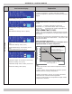
User Interface Display
Explanation
Installer Menu
Installer Menu
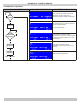
Installer Menu structure includes:
• User 'Menu' can be accessed by pressing 'Menu' key on
user interface.
• Installer'Menu'canbeaccessedbyrstpressingand
holding the 'Enter' key continue to hold and at the same
time press and hold the 'Menu’ key for 5 seconds. (You
mustpressandholdthe'Enter'keyrstthenpressand
hold the 'Menu' key).
• ‘Boiler Status’ submenu – Monitors detail boiler status
parameterssuchasamesignal,fanspeedsandstored
error codes.
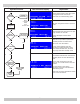
• ‘BoilerCong’submenu–Modiesgeneralboilersettings.
• ‘CHSettings’submenu–ModiesadvancedCentral
Heatingsettingsincludingoutdoorresetcurveparameters
and boost function.
• ‘DHWSettings’–ModiesDomestichotWatercontrolsettings
such as DHW priority time.
• ‘Cascade Settings’ - Refer to Multiple Boiler Manual.
• ‘System Test’ – Tool aids setup of boiler installation or
diagnosis of common problems.
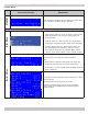
Boiler Status
CombustionairBlowerprovidesairowthroughCombustionand
Vent systems.
Fan speed status screen indicates actual and operational fan
speedsinRPM,high,lowandignitionpowerspeedsettings.
Settings are for information only to aid in troubleshooting.
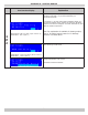
Boiler equipped with ionization rod to detect presence of
combustionusingamerecticationmethod.Whenameis
present,ameionizationrodmeasuressmallDCoffsetcurrent
acrossametoground(i.e.burnersurface).
‘Flame’ screen in ‘Boiler Status’ submenu displays information
regardingameionizationsystem;forinformationonlyandused
in diagnosing combustion problems. See troubleshooting guide.
APPENDIX A - CONTROL MODULE