
User Manual


25
1"(2.54cm)
Maximum
Combustion
Air
Vent
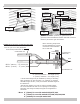
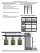
FIGURE 6-4 Side Wall Concentric Terminal FIGURE 6-5 Side Wall Concentric Terminal Multiple
Appliances
1" (25.4mm)
Maximum
Maintain 12"
clearance above
highest anticipated
snow level or grade
* See Note
Below
Vent
Combustion
Air
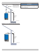
1" (25mm)
Maximum
Roof
Overhang
36"(0.9m) Minimum
Maintain 12"(30cm) US
(18"(46cm) Canada)
Clearance Above
Highest Anticipated
Snow Level Or Grade
12" (305mm) Minimum
*Must be less than 4" (102mm) or greater than 24"
(610mm) Horizontal distance between end bells of each air
intake to prevent ue gas recirculation.
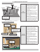
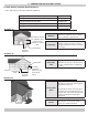
FIGURE 6-6 Concentric Terminal Connection
Note: Securing strap must
be eld installed to prevent
movement of termination
kit in side wall
Vent
Combustion Air
1"(25.4mm)
Maximum
**See
Note
*2 or 3" (51 or 77 mm) Diameter
PVC intake/combustion air
Combustion Air
*2" (
51mm)
Diameter = 41" Length (1.1m)
3" (77mm) Diameter = 47" Length (1.2m)
** Note Overall length may be modied by cutting or extending
both combustion air and vent pipes. 12" (305mm) is minimum
allowable length and 60" (1.2m) is maximum allowable length for
this dimension.
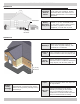
SDR-26 PVC (D2241) only may be used for extending pipes.
Do not use Schedule 40 PVC or use couplings to extend pipes.
Dimension will change if intake/vent pipes are lengthened or
shortened.
OD 3½" (
89mm)
- *2" (
51mm)
kit
OD 4½" (114mm) - 3" (77mm)
kit
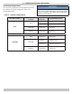
* Note: 2" (51mm) For use with models 050/075/100.
3" (77mm) For use with models 075/100/150/200/299
4" (101mm) For use with model 299
6 - COMBUSTION AIR AND VENT PIPING