
User Manual

15
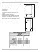
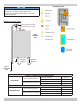
Piping Legend
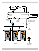
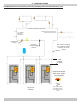
FIGURE 5-4 System Piping
NOTICE
Illustrations are meant to show system piping
concept only. Installer responsible for all
equipment and detailing required by authority
having jurisdiction.
System
Return
System
Supply
Safety Relief Valve
WALL
MOUNTED
ONLY
Pipe to
condensate
drain
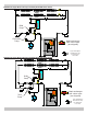
Table 3 - System Piping Congurations
Single Boiler
Two Pipe Zoned System
With Zone Valves gure 5-5
With Zone Pumps gure 5-6
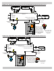
Primary/Secondary Pumping
Closed External Primary Loop
gure 5-7A
Open External Primary Loop gure 5-7B
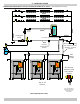
Multiple Boilers
Two Pipe Zoned System
With Zone Valves gure 5-8A
With Zone Pumps Not Shown
Primary/Secondary Pumping
Closed External Primary Loop gure 5-8B
Open External Primary Loop
gure 5-8C
5 - HYDRONIC PIPING