
Owner manual


14
NOTICE
Do not install valve between boiler and controls
manifold or relief valve.
11. Locate cast 1 1/4 x 1 1/4 x 3/4 tee and assemble on
long female adapter with 3/4” tapping
facing toward
front of boiler and joint is water tight.
12. Install Limit control mounting plug
in upper 3/4”NPT
port facing front.
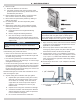
13. Install Limit control & harness assembly
. Loosen
mounting screw on bottom of limit control.
A. Mount control on mounting plug and tighten screw
to secure control. See
Figure 7.
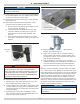
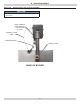
B. Conrm thermal limit/LWCO sensor bulb is fully
inserted to bottom of control well in top of rear
boiler section and secured with grommet. See
Figure 8.
C. Route thermal limit/LWCO sensor wire to control
and connect. See Figure 10, Page 15 and Figure 15,
Page 17.
Figure 7 - Control On Mounting Plug w/Screw
WARNING
Burn and scald hazard. Relief valve could
discharge steam or hot water during operation.
Check local codes for maximum distance from oor
or allowable safe point of discharge. Installation of
relief valve shall be consistent with ANSI/ASME Boiler
and Pressure Vessel Code, Section IV.
!
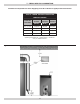
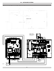
14. Install Relief Valve.
See
Figure 9
.
A. DO NOT pipe in area where freezing can occur. DO
NOT install shutoff valves, plugs or caps.
B. Locate 3/4”NPT x 90° street elbow. Install elbow using
3/4” NPT tapping in supply piping. Install elbow with
outlet facing directly up. Install relief valve with outlet
facing horizontally.
C. Pipe discharge of relief valve. Installation of relief
valve must be consistent with ANSI/ASME Boiler and
Pressure Vessel Code, Section IV.
Figure 8 - Grommet
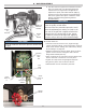
15. Check installation of liners and bafes (Not all
models)
. See Table 4, Page 16.
A. Check oval (4 section only) or V-shaped (certain 5
section models and all 6 and 7 section models) liner.
See
Figures 11 & 12
. Liner should be ush with front
edge of heat exchanger ns.
B. Flue way bafes (4, 5, 6 section only) are factory
installed in 3rd pass. Insure bafes are inserted in ue
way such that position tab touches casting between
2nd and 3rd Pass ue way. See
Figure 13, Page 16.
Efciency of boiler is based on insertion of ue way bafes
in 4, 5 and 6 section units. Bafes will generate lower gross
stack temperatures entering chimney. This has the potential
under certain operating conditions to cool ue gases below
dew point, creating condensation on interior chimney and
chimney connector surfaces. Remove bafes to increase
stack temperature if there are any signs of condensation in
chimney or chimney connector. Removing bafes alone may
not address condensation depending on other boiler and
heating system operating conditions.
NOTICE
Flue gas condensate is corrosive, which requires
special consideration and must be addressed
immediately.
8 - BOILER ASSEMBLY
TIGHTEN
SCREW
MOUNTING
PLUG
SENSOR IN WELL
WITH GROMMET
Figure 9 - Relief Valve