EXCELSIOR Models EXB4075 EXB4095 EXB4110 EXB5100 EXB5115 EXB5135 EXB6130 EXB6145 EXB6165 EXB7165 EXB7180 EXB7190 High Efficiency Oil Fired Hot Water Boiler INSTALLATION, OPERATION & MAINTENANCE MANUAL Manufactured by: ECR International, Inc. 2201 Dwyer Avenue, Utica NY 13501 web site: www.ecrinternational.com An ISO 9001-2008 Certified Company P/N 240009348, Rev.
EXCELSIOR OIL-FIRED CAST IRON HOT WATER BOILER Models EXB5100 EXB6130 Per Energy Star specifications, AFUE is rounded to the nearest whole percentage point. As such, these products qualify for Energy Star. Check our website frequently for updates: www.ecrinternational.com Information and specifications outlined in this manual in effect at the time of printing of this manual.
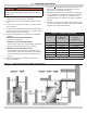
DIMENSIONS DIMENSIONS Sections 4 5 6 7 Dimension A Inches (cm) Flue Size Inches (cm) 5 5 5 6 (13) (13) (13) (15) 18 21 24 28 3 3/8 5/8 7/8 1/8 (46) (56) (64) (72)
TABLE OF CONTENTS 1 - Introduction............................................................................................................... 5 2 - Safety Information..................................................................................................... 6 3 - Before You Start......................................................................................................... 7 4 - Ratings & Capacities......................................................................................
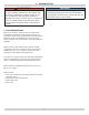
1 - INTRODUCTION ! WARNING NOTICE Installations of boilers and venting shall be done only by a qualified expert and in accordance with this manual. Installing or venting a boiler or any other oil appliance with improper methods or materials may result in serious injury or death due to fire or to asphyxiation from poisonous gases such as carbon monoxide which is odorless and invisible. Surface rust on cast iron sections may be attributed to manufacturing process as well as condensation during storage.
2 - SAFETY INFORMATION 2.1 General ! WARNING Boiler installation shall be completed by qualified agency. Construction materials of appliance and products of combustion and fuel contain alumina, silica, heavy metals, carbon monoxide, nitrogen oxides, aldehydes and /or other toxic or harmful substances which can cause death or serious injury and which are known to the State of California to cause cancer, birth defects and other reproductive harm.
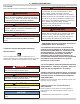
3 - BEFORE YOU START 3.1 Installation and Operation 3.2 Prior To Installing The Boiler 1. Do not operate unit if any control, switch, components 2. 3. 4. 5. 6. 7. 8. 9. 10. • Verify you have selected right size boiler with proper capacity. AHRI rating of boiler selected should be greater than or equal to calculated peak heating load (heat loss) for building or area(s) served by boiler and associated hot water heating systems. Use heat loss calculations based on approved methods.
4 - RATINGS & CAPACITIES Table 1 RATINGS & CAPACITIES OIL-FIRED HOT WATER BOILERS AFUE [%] Min. relief Valve Capacity [Mbh] Max. Water Temp [°F] Chimney Liner Size Round [Inches] Chimney Liner Size [Square Inches] Flue Size [Inches] 65 86.0 91 250 6 6 3/4 5 99 65 85.0 115 250 6 6 3/4 5 115 65 84.0 132 250 6 6 3/4 5 106 65 86.5 122 250 6 6 3/4 5 121 65 85.0 139 250 6 6 3/4 5 161 140 65 84.0 161 250 7 6 3/4 5 182 159 138 65 86.
5 - LOCATING THE BOILER 7. Fresh air for combustion and ventilation must be avail- ! WARNING Fire hazard. Do not be install on carpeting. Failure to follow these instructions could result in death or serious injury. 8. 1. Boiler is suitable for installation on combustible flooring. Do not install boiler on carpeting. 2. Locate boiler in front of final position before removing 3. 4. 5. 9. crate. Locate unit so vent pipe connection to chimney will be short and direct.
6 - INSTALLATION REQUIREMENTS Figure 2 - General Requirements For A Typical Installation LIMIT RELIEF VALVE CHECK LOCAL CODES FOR MAXIMUM DISTANCE FROM FLOOR, OR OTHER ALLOWABLE SAFE POINT OF DISCHARGE. NOTICE Shut off manual fuel supply valve if burner is shut down for extended period of time.
7 - FRESH AIR FOR COMBUSTION ! WARNING Alternate method for boiler located within confined space: Use indoor air if two permanent openings communicate directly with additional space(s) of sufficient volume such that the combined volume of all spaces meet criteria for unconfined space. Size each opening for minimum free area of 1 square inch per 1,000 BTU per hour input of all equipment in spaces, but not less than 100 square inches. Asphyxiation, fire hazard.
7 - FRESH AIR FOR COMBUSTION Fresh Air Duct Capacities For Ducts Supplying Fresh Air To Boiler In Tightly Constructed Houses Table 3 - FRESH AIR DUCT CAPACITIES THROUGH LOUVERS ¼” Mesh Screen Wood Louvers Metal Louvers (Btuh)* (Btuh)* (Btuh)* 3 ½” x 12” 144,000 36,000 108,000 8” x 8” 256,000 64,000 192,000 8” x 12” 384,000 96,000 288,000 8” x 16” 512,000 128,000 384,000 Fresh Air Duct Size *Btuh = British Thermal Units per hour based on opening covered by ¼” mesh screen , wood louver
8 - BOILER ASSEMBLY 1. Remove Crate Figure 5 - Reversible Hinge A. Remove all fasteners at crate skid. B. Lift outside container and remove all other inside protective spacers and bracing. Remove burner and miscellaneous parts boxes. 2. Remove Boiler from skid. Boiler is secured to base with 4 screws. Remove all securing hardware. 3. Move boiler into permanent position by sliding or walking into place. 4. Do not drop boiler. Do not bump boiler jacket against floor. 5. Open burner swing door.
8 - BOILER ASSEMBLY NOTICE Figure 8 - Grommet Do not install valve between boiler and controls manifold or relief valve. 11. Locate cast 1 1/4 x 1 1/4 x 3/4 tee and assemble on 12. 13. long female adapter with 3/4” tapping facing toward front of boiler and joint is water tight. Install Limit control mounting plug in upper 3/4”NPT port facing front. Install Limit control & harness assembly. Loosen mounting screw on bottom of limit control. A.
8 - BOILER ASSEMBLY Figure 10 - Supply Piping and Control Assembly NOTICE Do not install valves between boiler and controls manifold or relief valve.
8 - BOILER ASSEMBLY Figure 11 - Oval Liner 16. Connect Field Wiring. See “13 - Electrical Connections” on page 34. A. Route wire harness from burner to Limit control through rear jacket panel. See Figure 15, Page 17. Connect molex plug on burner wire harness to its receptacle on limit control. B. If optional manual reset high temperature limit is not used, ensure supplied jumper is installed. C. Connect the wiring harness from limit control to circulator. See Figure 15, Page 17. D.
8 - BOILER ASSEMBLY B. Use hand wrench to tighten door hardware and start with non-hinged side. Use alternating tightening method from non-hinged side to hinged side to tighten door equally until sealed without applying excessive torque. Never tighten hinged side flange bolt first or tighten either piece of hardware 100% without using alternating tightening method described above. Figure 14 - Circulator Wiring NOTICE When securing burner swing door, make sure door is drawn-in equally on both sides.
9 - BOILER SYSTEM PIPING 9.1 Connect System Supply And Return Piping 9.2 Bypass Piping To Boiler See Piping Diagrams for illustrations for this section. Connect system supply and return piping to correct boiler fittings. Bypass piping may be required for applications listed below. Failure to do so may cause damage due to thermal shock and sustained condensation within the boiler. Size system circulator to supply sufficient flow (GPM) to allow 20°F temperature differential in system.
10 - HYDRONIC PIPING Figure 17 - Standard Near Boiler Piping Piping Diagram Legend 19
10 - HYDRONIC PIPING Figure 18 - Piping and Wiring Single Zone System With Domestic Hot Water DHW Priority DHW Heater FIGURE 18 INDIRECT WATER HEATER, AQUASTAT OR THERMOSTAT TANK CONTROL T-STAT THERMOSTAT DATA PORT + ELECTRONIC FUSE + ZONE 2 T 1 T W + R T 2 T W ZONE 1 + R COMMON 24 VAC @ 1 VA ZONE 2 CT TO EXTRA ZONE MODULE PRIORITY ON X-X PRIORITY ON ARM-2P CONTROL WITH PRIORITY X1 X1 X2 X2 ISOLATED SWITCH ISOLATED SWITCH L 1 N L 2 PRIORITY ZONE 2 120VAC CIRCULATORS CIRC DHW
10 - HYDRONIC PIPING Figure 19 - Multi-Zone Piping and Wiring With Zone Valves And Domestic Hot Water Priority (With Zone Valve) * (SEE FIGURE 20) ON FIGURE 19 ZONE VALVE / PUMP PRIORITY ZR-ZC DPM-2 INDIRECT WATER HEATER, AQUASTAT OR THERMOSTAT TANK CONTROL OPTION SWITCHES T-STAT T-STAT KEY ON OFF T-STAT 24VAC FROM TRANSFORMER T C T T T T T T T 24 VAC R TO DPM-2 X X Z1 STATUS PRIORITY ON PRIMARY PUMP PRIORITY PUMP X-X CONTACT ZR ON HYDROSTAT MODEL 3250 Z2 Z3 Z4 ZONE VALVE / PUMP
10 - HYDRONIC PIPING Figure 20 - Piping and Wiring Multizone System With Zone Valves And Domestic Hot Water Priority (With Circulator) ON FIGURE 20 ZONE VALVE / PUMP PRIORITY ZR-ZC DPM-2 INDIRECT WATER HEATER, AQUASTAT OR THERMOSTAT TANK CONTROL OPTION SWITCHES T-STAT T-STAT KEY ON OFF T-STAT 24VAC FROM TRANSFORMER T C T T T T T T T 24 VAC R X TO DPM-2 X Z1 STATUS PRIORITY ON PRIMARY PUMP PRIORITY PUMP X-X CONTACT ZR ON HYDROSTAT MODEL 3250 Z2 Z3 Z4 ZONE VALVE / PUMP PRIORITY ZR-Z
10 - HYDRONIC PIPING Figure 21 - Piping and Wiring Multi-Zone System With Circulators And Domestic Hot Water Priority FIGURE 21 INDIRECT WATER HEATER, AQUASTAT OR THERMOSTAT TANK CONTROL T-STAT T-STAT THERMOSTATS DATA PORT PRIORITY ZONE + ELECTRONIC FUSE ZONE 2 ZONE 3 ZONE 4 COMMON 1 T R TW 2 T R TW 3 T R TW 4 T R TW Z 24 VAC @ 1VA + + T-STAT 24AC PRIORITY ON HYDROSTAT MODEL 3250 30 VA TO EXTRA ZONE MODULE COMMON X-X ZR-ZC + ZONE 1 ZONE 2 ZONE 3 PRIORITY ON ZONE 4 ARM-4P CON
10 - HYDRONIC PIPING Figure 22 - Primary/Secondary Piping And Wiring With Circulators And Domestic Hot Water MAX = 4 X DIAMETER CLOSELY - SPACED TEES BOILER PUMP 24
10 - HYDRONIC PIPING FIGURE 22 INDIRECT WATER HEATER, AQUASTAT OR THERMOSTAT TANK CONTROL T-STAT T-STAT THERMOSTATS DATA PORT PRIORITY ZONE + ELECTRONIC FUSE 1 TW Z ZONE 2 TR TW 2 ZONE 3 T R TW 3 ZONE 4 TR TW 4 COMMON TR 24 VAC @ 1VA + + T-STAT 24AC PRIORITY ON HYDROSTAT MODEL 3250 30 VA TO EXTRA ZONE MODULE COMMON X-X ZR-ZC + ZONE 1 ZONE 2 ZONE 3 PRIORITY ON ZONE 4 ARM-4P CONTROL WITH PRIORITY X X ISOLATED SWITCH L ZC ZR 1 PRIORITY N L 2 ZONE 2 N L 3 ZO
10 - HYDRONIC PIPING Figure 23 - Piping and Wiring Primary/Secondary Multi Zone System Piping With Zone Valves And Domestic Hot Water (With Zone Valve) ZONE 1 (PRIORITY ZONE)* * * USE FULL PORT ZONE VALVE. FOR OPTIMUM TANK PERFORMANCE, CONSIDER USING ZONE SEE FIGURE 24 CIRCULATOR.
10 - HYDRONIC PIPING ON FIGURE 23 ZONE VALVE / PUMP PRIORITY ZR-ZC DPM-2 INDIRECT WATER HEATER, AQUASTAT OR THERMOSTAT TANK CONTROL OPTION SWITCHES T-STAT T-STAT KEY ON OFF T-STAT 24VAC FROM TRANSFORMER T C T T T T T T T 24 VAC R TO DPM-2 X X Z1 STATUS PRIORITY ON PRIMARY PUMP PRIORITY PUMP X-X CONTACT ZR ON HYDROSTAT MODEL 3250 Z2 Z3 Z4 ZONE VALVE / PUMP PRIORITY ZR-ZC DPM-2 120VAC TO TRANSFORMER ZC ON L 120 VAC TO XFRM N 120VAC N L PRIMARY PUMP L N PRIORITY PUMP L N AZ
10 - HYDRONIC PIPING Figure 24 - Piping And Wiring Primary/Secondary Piping With Zone Valves And Domestic Hot Water (With Circulator) ZONE VALVE MAX = 4 X DIAMETER CLOSELY - SPACED TEES 28
10 - HYDRONIC PIPING ON FIGURE 24 ZONE VALVE / PUMP PRIORITY ZR-ZC DPM-2 INDIRECT WATER HEATER, AQUASTAT OR THERMOSTAT TANK CONTROL OPTION SWITCHES T-STAT T-STAT KEY ON OFF T-STAT 24VAC FROM TRANSFORMER T C T T T T T T T 24 VAC R TO DPM-2 X X Z1 STATUS PRIORITY ON PRIMARY PUMP PRIORITY PUMP X-X CONTACT ZR ON HYDROSTAT MODEL 3250 Z2 Z3 Z4 ZONE VALVE / PUMP PRIORITY ZR-ZC DPM-2 120VAC TO TRANSFORMER ZC ON L 120 VAC TO XFRM N 120VAC N L PRIMARY PUMP L N PRIORITY PUMP L N AZ
10 - HYDRONIC PIPING Figure 26 Bypass Piping (Fixed Low Temperature Only) Adjust two throttling valves to maintain at least 130°F - 140°F in boiler return.
10 - HYDRONIC PIPING Figure 27 - Bypass Piping (4-Way Valve Option With Circulator On Supply Side) TO SYSTEM FROM SYSTEM WATER INLET EXPANSION TANK BOILER ALTERNATE CIRCULATOR LOCATION Figure 28 - Recommended Piping for Combination Heating and Cooling (Refrigeration) System CIRCULATOR PRESSURE REDUCER VALVE SHUT-OFF VALVE CHECK VALVE BALL VALVE AIR SEPARATOR WATER CHILLER 4-WAY MIXING VALVE HOSE BIB FLOW CONTROL VALVE BOILER SHUT OFF VALVES SHUT OFF VALVES AIR CUSHION TANK CIRCULATOR RETUR
11 - FUEL SUPPLY PIPING 11.1 Installation of oil tank and piping shall conform to requirements of authority having jurisdiction or in absence of such requirements National Board of Fire Underwriters . In addition, refer to NFPA 31 (U.S.) or CSA B139 (Canada) Figure 30 - Double Pipe Oil Line Installation of oil storage tank, vent, fill pipe and caps shall conform to requirements of authority having jurisdiction. • In no case should vent pipe be smaller than 1¼" I.P.S.
12 - ANTIFREEZE IN THE SYSTEM 12.1 Antifreeze added to boilers must be nontoxic, and must be of type specifically intended for use in closed hydronic heating systems. Under no circumstances should automotive antifreeze be used. Antifreeze used in any boiler may reduce capacity by 10% or more and increase fuel consumption. See Table 6 and 7. Table 7 - PIPING WATER VOLUMES Table 6 - BOILER WATER VOLUMES Number of Boiler Section 4 5 6 7 Total Volume (Gallons) 3.6 4.3 5.1 5.
13 - ELECTRICAL CONNECTIONS ! WARNING 13.1 Electrical wiring shall conform to requirements of authority having jurisdiction or in absence of such requirements ANSI/NFPA No. 70, in Canada shall be in accordance with the Canadian Electrical Code C22.2. Electrical shock hazard. Turn OFF electrical power supply at service panel before making electrical connections. Failure to do so could result in death or serious injury.
14 - CHIMNEY AND VENTING CONNECTIONS 3. Chimney Inspection – Prior to installation of any new or 14.1 Chimney Venting Oil fired boilers with connections to vents or chimneys, vent installation shall conform to requirements of authority having jurisdiction or in absence of such requirements NFPA 31 Installation Of Oil Burning Equipment (U.S.) or CSA B139 (Canada) and applicable provisions of local building codes.
14 - CHIMNEY AND VENTING CONNECTIONS 14.2 Vent and Vent Connector Table 9 - Pressure Drop Between 1. Vent connector should be kept as short as possible. 2. 3. Over-Fire & Breech Horizontal length of vent connector should not be greater than 10 feet. Type L Vent pipe or other suitable material may be used for vent connector if flue temperature is less than 570° F.
14 - CHIMNEY AND VENTING CONNECTIONS Figure 31 - Proper Draft Regulator Locations Figure 32 - Typical Chimney Locations Figure 33 - Pressure Tapping for Checking Draft Minimum height must be at least 3 Ft higher than highest part of passage through roof. Must be at least 2 FT higher than any neighboring object within 10 Ft. Must have unobstructed top opening. 1/4”NPT TEST PORT FOR OVER-FIRE MEASUREMENT Must be at least 4 inches thick and be tight.
15 - FILLING BOILER ! WARNING NOTICE Boiler maximum operating pressure is posted on ASME data label located on front lower leg of boiler. Never exceed this pressure. Do not plug relief valve. Fire, burn, asphyxiation hazard. Turn off service switch to boiler to prevent accidental firing of burner outside combustion chamber. Disconnect burner power cord from wire harness in front jacket. Tighten swing door fastener completely when service is complete.
16 - OPERATING THE BOILER - SYSTEM START-UP 16.1 Setting The Limit Control Figure 34 - Limit Setting can be verified using TEST/SETTINGS button. See Page 41. 16.2 Setting High Limit To adjust, turn HI TEMP dial A until desired setting is displayed. See Figure 34. Overall range of High limit setting is from 100°F to 220°F (82° C to 104° C). High limit (HL) on limit control is factory set at 190°F. Temperature setting may be varied to suit requirements of installation.
16 - OPERATING THE BOILER - SYSTEM START-UP 16.6 Activating Thermal Pre-Purge (optional) Activation of this feature is not recommended for boilers with tankless coils. • Limit has thermal pre-purge feature to maximize efficiency. When activated, control will purge higher boiler temperatures down to 135°F at start of any thermostat call and supply latent energy in boiler to heating zone calling. • During purge cycle, display will indicate PUR.
16 - OPERATING THE BOILER - SYSTEM START-UP 6 ECONOMY TARGET Economy feature is active, limit control continually sets target temperatures below high limit setting to maximize fuel efficiency. When boiler water reaches target temperature, LED illuminates and burner shuts down. Boiler water will continue to circulate and heat the house as long as thermostat call continues. LED will stay lit until boiler temperature drops below differential set point at which point boiler will be allowed to fire again.
16 - OPERATING THE BOILER - SYSTEM START-UP 16.9 Oil Burner - Beckett AFG ! WARNING NOTICE Fire, burn, asphyxiation hazard. Do not loosen or remove any oil line fittings while burner is in operation. Failure to follow these instructions could result in death or serious injury. Instructions are for Beckett AFG with Beckett Genisys primary control. For other burners, refer to manufacturer’s manual. Nozzle and air settings are given in Table 14 page 50. ! WARNING Fire, burn, asphyxiation hazard.
16 - OPERATING THE BOILER - SYSTEM START-UP ! CAUTION IV. After 60 second recycle period, control will try to restart system. Do not run boiler unattended until following procedure is completed. Failure to follow these instructions could result in minor or moderate injury. V. After 15 second lockout time, control will lock out burner and reset button will flash. Verify burner, motor and igniter are off and burner solenoid valve (if used) is not energized. E.
16 - OPERATING THE BOILER - SYSTEM START-UP E. Ignition Carry-over. Once flame is established, igniter remains on for 10 additional seconds to ensure flame stability. F. Run. Flame is sustained until call for heat is satisfied. Burner is then sent to Motor-Off Delay, if applicable, or it is shut down and sent to Standby. G. Recycle. If flame is lost while burner is firing, control shuts down burner, enters 60 second recycle delay, and repeats ignition sequence.
16 - OPERATING THE BOILER - SYSTEM START-UP C. After installing nozzle, reassemble nozzle line electrode assembly and set electrode tip spacing. D. Electrode tip spacing may need to be set prior to reassembling nozzle line electrode assembly. Refer to figures on following pages for setting electrode tip spacing on Beckett. NOTICE Before starting or resetting control from restricted lockout state, troubleshoot heating system for root cause(s) of lockout. 8. Genisys Control - Resetting From Restricted 16.
17 - OIL BURNER, NOZZLE, & AIR SETTINGS Figure 40 - Beckett Electrode Tip Adjustments Standard Dimensions (L2) Heads Figure 39 - Beckett Electrode Tip Adjustments Standard Dimensions (L1, V1) Heads Figure 41 Figure 42 - Beckett Check/Adjust “Z” Dimensions L1 & L2 Heads - Beckett Check/Adjust ‘Z’ Dimension V1 Heads L1/L2 Heads V1 heads See Figure 39. The important “Z” dimension is distance from leading edge of head to end of air tube.
17 - OIL BURNER, NOZZLE, & AIR SETTINGS Figure 44 -Riello Turbulator Setting Figure 43 - Riello Electrode Setting Turbulator Setting A. Loosen nut (1) turn SCREW (2) until INDEX MARKER (3) is aligned with correct index number as per Burner Settings Table. B. Tighten RETAINING NUT (1). NOTE: Zero and four are scale indicators only. From left to right, first line is 4 and last line 0. On some models, scale indicators are 0 and 3.
17 - OIL BURNER, NOZZLE, & AIR SETTINGS Table 13 - Beckett Chimney Vent Preliminary Burner Settings Burner settings provided are for initial startup only. Final adjustments must be made using combustion test instruments. TABLE 13a: BECKETT CHIMNEY PRELIMINARY BURNER SETTINGS Rated Air Air AFUE Band Shutter Efficiency [%] Boiler Model Head Type Static Plate Insertion Depth Firing Rate [GPH] Combustion liner Nozzle Mfr. Nozzle Type Pump Pressure [PSI] “Z” Head Setting 4075 L2 3.375U 2.625 0.
17 - OIL BURNER, NOZZLE, & AIR SETTINGS Table 14 - Beckett NX (Direct Vent) Preliminary Burner Settings Burner settings provided are for initial startup only. Final adjustments must be made using combustion test instruments. TABLE 14a: BECKETT DIRECT VENT PRELIMINARY BURNER SETTINGS Pressure Switch Setpoint Rated AFUE Efficiency [%] 1.5 0.65" WC 86.0 155 4.0 0.65" WC 85.0 0.75x45B 175 4.0 0.85" WC 86.5 Hago 1.00x60B 140 1.8 0.85" WC 85.0 V5 Delavan 1.10x60B 150 2.5 0.85" WC 84.
17 - OIL BURNER, NOZZLE, & AIR SETTINGS Table 15 - Riello 40F Chimney Vent Preliminary Burner Settings Burner settings provided are for initial startup only. Final adjustments must be made using combustion test instruments. TABLE 15: RIELLO 40F CHIMNEY VENT PRELIMINARY BURNER SETTINGS Firing Rate [GPH] Combustion Liner Nozzle Mfr. Nozzle Type Pump Pressure [PSI] Rated AFUE Efficiency [%] Boiler Model Head Type Insertion Depth 4075 Reverse 2.75" 0.75 Oval Delavan 0.65x60W 150 1 3.6 86.
17 - OIL BURNER, NOZZLE, & AIR SETTINGS Table 16 - Riello 40BF (DIRECT VENT) Preliminary Burner Settings Burner settings provided are for initial startup only. Final adjustments must be made using combustion test instruments. Table 16: RIELLO 40BF DIRECT VENT PRELIMINARY BURNER SETTINGS Inser- Firing Comtion Rate bustion Depth [GPH] Liner Nozzle Mfr. Nozzle Type Pump Pressure [PSI] Boiler Model 4075 Reverse 2.75" 0.75 Oval Delavan 0.65x60W 150 3 5.0 0.25" WC 86.0 4095 Standard 1.75" 0.
17 - OIL BURNER, NOZZLE, & AIR SETTINGS Table 17 - Carlin (CHIMNEY VENT) Preliminary Burner Settings Burner settings provided are for initial startup only. Final adjustments must be made using combustion test instruments. TABLE 1 - CARLIN SETTINGS BOILER NO. INSERTION DEPTH FIRING RATE COMBUSTION LINER NOZZLE MFR. NOZZLE TYPE PUMP PRESSURE [PSI] HEAD BAR AIR BAND SETTING Rated AFUE Efficiency [%] 4075 3.00” 0.75 OVAL DANFOSS 0.60 x 60 AS 160 0.60/0.65 25% 86.0 4095 3.00” 0.
18 - MAINTENANCE ! DANGER 18.3 Relief Valve • Test relief valve for proper operation. Refer to valve manufacturer’s instructions packaged with relief valve. Before servicing, turn off electrical power to boiler at service switch. Turn off fuel supply to burner Failure to comply will result in death or serious injury. 18.4 Conventional Expansion Tank See “Equipment And Accessories” section. NOTICE 18.
18 - MAINTENANCE Steps to inspect, clean and/or replace control well: • Continue to circulate water for few hours. • Stop firing boiler. • Drain system in manner and to location that hot water can be discharged safely. • Remove plugs from all available returns and wash water side of boiler as thoroughly as possible, using high-pressure water stream. • Refill system with fresh water. 1. Turn off electric service to boiler controls. 2. Drain boiler water to level below tapping for control well. 3.
19 - OIL BOILER / BURNER CLEANING INSTRUCTIONS 2. Clean combustion chamber and baffles. Use wire ! DANGER or fiber bristle brush to clean surfaces of combustion chamber and baffles. Vacuum all of loose debris in bottom of combustion chamber. 3. After cleaning: Vacuum all remaining debris as necessary. Inspect burner swing door insulation, and rope gasket for signs of damage. If damaged, replace as needed. 4. Re-assemble boiler. A. Insert liner and baffles (if equipped) into correct flue way.
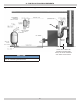
19 - OIL BOILER/BURNER CLEANING INSTRUCTIONS Figure 46 - Cleaning the Boiler FLUE BRUSH 3RD PASS FLUE BRUSH BRISTLE BRUSH VACUUM HOSE FRONT VIEW COMBUSTION CHAMBER & 2ND PASS 56 VACUUM HOSE
20 - TROUBLESHOOTING 20.1 Combustion I. No oil to burner. II. Shortened electrodes A. Nozzles- See “17 - Oil Burner, Nozzle, & Air Settings” on page 46. B. Fuel leaks - Any fuel leak between pump and nozzle is detrimental to good combustion results. Look for wet surfaces in air tube, under ignitor, and around air inlet. Repair any such leaks as they may cause erratic burning of fuel and in extreme case may become fire hazard. C.
20 - TROUBLESHOOTING IF YOUR SYSTEM IS NOT HEATING OR NOT GIVING ENOUGH HEAT . . . POSSIBLE CAUSE WHAT TO DO Thermostat is not set correctly Reset thermostat Burner is not operating properly Adjust burner per instructions. No electric power to boiler Check over-current protection. Check to be sure electric power supply circuit is “ON”. There may be as many as 3 safety shut-off switches installed. Look for a red plate which may be on the service switch.
21 - EQUIPMENT AND ACCESSORIES 21.6 Conventional Expansion Tank (Not Provided) 21.1 Limit Relay Control (provided) Water temperature limit control in limit relay is adjustable. See Limit instructions for how to set limit temperature. In a properly assembled system, expanding water flows into an expansion tank. 21.
21 - EQUIPMENT AND ACCESSORIES Figure 47 - Grundfos Pump Curve 5 15 4 m Head 2 1 10 Head (feet) 3 5 0 US GPM 3 m /h Model UP 15-42F 5 10 15 1 2 3 Watts Volts Amps 85 115 0.74 20 4 5 Capacitor 10µF/180V* *Supplied with pump Figure 48 - Taco Pump Curve Model 007-F5 Volts Amps 115 0.
NOTES
NOTES 62
Date Service Performed Company Name & Tech Initials Company Address & Phone # SERVICE RECORD 63
DUNKIRK BOILERS 2201 Dwyer Avenue, Utica NY 13501 web site: www.ecrinternational.