
Manual

16
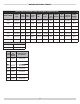
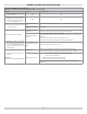
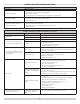
Condition 2: Burner starts then locks out on safety with red indicator light fl ashing.
Procedure Status Corrective Action
1. Reset oil primary control by pushing in and releasing
red reset button.
Indicator light stops
fl ashing.
Go to Step 2.
Indicator light
continues to fl ash at
1/2 second on, 1/2
second off rate.
Verify that the control is not in restricted mode. (See notes at end of this
table.). If not in restricted mode, replace Aquastat
2. Listen for spark after burner turns on (after 2 second
delay).
Ignition is off
Spark igniter could be defective. Check for line voltage at igniter
terminals. If line voltage is present, replace R7484.
Ignition is on. Go to Step 3.
Ignition is on but no
oil is being sprayed
into the combustion
chamber.
Wait for “Valve ON” delay to complete.
Check oil supply.
Ensure BVS bypass contact close and bypass pressure switch for
10-seconds.
After 10-seconds, check pressure switch on BVS to ensure closed.
Pressure switch open.
Check pressure tubes for proper connection or possible obstructions.
Check venting for blockage.
Check combustion air intake for blockage.
Check pressure switch operation.
Check oil line valve.
Check for fi lter blockage or seized oil pump.
3. Check indicator light after fl ame is established, but
before oil primary control locks out.
Indicator light is
on until the control
locks out and starts
fl ashing during
lockout.
Check Aquastat
Indicator light stays
off.
Go to step 4.
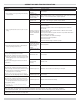
4. Check cad cell sighting for view of fl ame.
• Disconnect line voltage power and open line switch.
• Unplug cad cell and clean cad cell face with soft clothe.
Check sighting for clear view of fl ame. Replace cad
cell in socket.
• Reconnect line voltage power and close line switch.
• Start burner.
Burner locks out. Go to step 5.
Burner keeps
running.
System is OK.
5. Check cad cell.
• Disconnect line voltage power and open line switch.
• Remove existing cad cell and replace with new cad cell.
• Disconnect all wires from thermostat terminals to
ensure that there is no call for heat.
• Reconnect line voltage power and close line switch.
• Expose new cad cell to bright light such as a fl ashlight.
Indicator light is on. Remount control onto burner housing. Go to step 6.
Indicator light is off. Go to step 6.
6. Check cad cell bracket assembly.
• Disconnect line voltage power and open line switch.
• Remove cad cell wires from quick connect connectors
on the Aquastat and leave control lead wires open.
• Apply power to device.
• Place jumper across cad cell terminals after burner
motor turns on.
Indicator light is on. Replace cad cell bracket assembly.
Indicator light is off. Replace Aquastat.
NOTE: Restricted Mode - (Limited Reset): In order to limit the accumulation of unburned oil in the combustion chamber, the control can be reset only
3 times, after which, the control locks out. The reset count returns to zero each time a call for heat is successfully completed.
To reset from Restricted Mode: press and hold the reset button for 30 seconds. When the LED fl ashes twice, the device has reset.
NOTE: Disable function: Pressing and holding the reset button will disable all functions until the button is released. The burner will restart at the
beginning of the normal heat cycle on safety check.
OPERATION AND TROUBLESHOOTING