
Troubleshooting guide

3.0 INSTALLATION
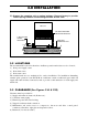
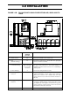
FIGURE 3.3B: FOR UNITS WITH SINGLE SIDE RETURN AIR, WCPS 640B TO
1520B
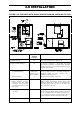
Side Recommended
Minimum
Clearance
Remark
1.) Return air, front 48" For proper air intake to the condenser coil.
2.) Rear
(Vertical discharge)
48" For access to compressors, controls, filter drier, sight glass,
fan motor and drive assembly.
3.) Top
a.) Vertical discharge
b.) Rear discharge
Please refer table
for proper duct
connection.
2”
For proper duct connection to avoid high discharge air
turbulence which can create excessive noise or drumming at
discharge duct.
For removal of the panels, if necessary.
4.) Side with piping
connection
36" For proper piping connection and access to valve fittings,
strainer, thermometer, pressure gauges, flow switch etc.
which may be fitted to the condenser inlet and outlet
pipings. Also for access to fan motor and drive if located on
this side.
5.) Side opposite of piping
connection
60 For brush cleaning of inner water tubes of shell and tubes
condenser(s). Brush cleaning of inner water tubes can be
accomplished by removing the end water boxes (opposite
piping connection) of each condenser. Also for access to fan
motor and drive if located on this side.
6.) Bottom - Allow enough clearance to trap the emergency drain line.