
Troubleshooting guide
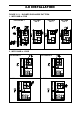

3.0 INSTALLATION
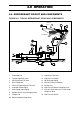
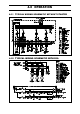
FIGURE 3.5.2 SUGGESTED METHOD FOR CONNECTING SUPPLY DUCT
Model A B
68-160 40 25
190-510 60 35
570-1520 80 50
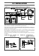
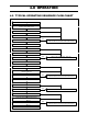
3.6 EVAPORATOR SECTION
1.) For all models, return air is through front of the unit.
2.) The standard unit has three or four row deep coils.
3.) The thermal expansion valve(s) and distributor(s) are at the left end of the units viewing
from the return airside (same as condenser and drain piping connections).
4.) Filters are located at the return airside (refer to table for quantities and sizes). It can be
taken out for servicing by removing one side of the filter holding frame.
5.) Fans rpm shall be selected within the range of the Blower Performance Table. For
operation outside the Blower Performance Table, consult factory or nearest Dunham-Bush
representative.
6.) Maximum motor hp size for each model shall be observed. If larger than standard motor
size is required, consult factory or nearest Dunham-Bush representative.
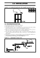
7.) Condensate drain should be trapped as shown in Figure 3.6.
FIGURE 3.6: CONDENSATE DRAIN TRAP