Form No: MM0214A / MM0215A ® Products That Perform . . .
TABLE OF CONTENTS MANUAL INDEX PAGE 1.0 INTRODUCTION................................................................................................................................................................... 3 2.0 GENERAL INFORMATION 2.1 SAMPLE NOMENCLATURE ................................................................................................................................................. 4 2.2 2.3 2.4 RECEIVING, INSPECTION AND PACKAGING..............................................
1.0 INTRODUCTION This equipment is factory manufactured and tested water-cooled package for the purpose of air-conditioning. It consists mainly of a direct expansion evaporator coil(s) with thermal expansion valve, scroll compressor(s) and water-cooled cleanable shell and tube condenser(s).
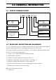
2.0 GENERAL INFORMATION 2.1 SAMPLE NOMENCLATURE 6 WCP S 640 B Q P Blank - 50Hz 6 - 60Hz Blank - R22 P - R407c Water Cooled Packaged Blank - Standard Q - Special Generation S - Scroll Compressor R - Reciprocating Compressor Model Code 2.2 RECEIVING, INSPECTION AND PACKAGING As soon as the unit is received, it should be inspected for any damage during transit. Make a separate written request if there is any damage on the carrier's delivery order.
2.0 GENERAL INFORMATION 2.) Supply air plenum. 3.) Return air grille and integral filter frame. 4.) Hot water heating coils or electric reheaters. 5.) Compressor time delay relay. 6.) Factory wired starter board. 7.) Hot gas by pass, oil separator and suction accumulator. 8.) Copper, hydrophilic fins or tinned coated copper fins. 9.) Pressure gauges. 10.) Suction stop valve(s), discharge stop valve(s) and liquid stop valve(s). 11.) External spring vibration isolators for blower fan and drive assembly. 2.
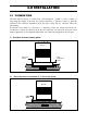
3.0 INSTALLATION 3.1 FOUNDATION The unit shall be placed on a flat, level, solid foundation ( plinth ) or floor capable of supporting the weight of the unit. No special foundation or vibration isolator is generally required as the vibration transmitted from the units casing will not adversely effect the surrounding.
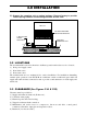
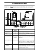
3.0 INSTALLATION iii.) Support the complete unit on spring isolators. Request factory to provide correct spring isolators and mounting brackets at base units. WCPS-B FACTORY PROVIDED MOUNTING BRACKETS 2" DEFLECTION SPRING ISOLATORS NON-SKID NEOPRENE PAD 6-1/2" 1" FLOOR 3.2 LOCATIONS The recommended location for the units to facilitate operation and reduce cost is to locate it: 1.) Near power supply source 2.) Near drain source 3.
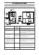
3.0 INSTALLATION FIGURE 3.3A: FOR UNITS WITH SINGLE SIDE RETURN AIR, WCPS 68B TO 570B Side Recommended Minimum Clearance Remark 1.) Return air, front 48" For proper air intake to the condenser coil. 2.) Rear (Vertical discharge) 48 For access to compressors, controls, filter drier, sight glass, fan motor and drive assembly. Unless otherwise specified, compressors and controls are fitted for access from rear sides of units. 3.) Top a.
3.0 INSTALLATION FIGURE 3.3B: FOR UNITS WITH SINGLE SIDE RETURN AIR, WCPS 640B TO 1520B Side Recommended Minimum Clearance Remark 1.) Return air, front 48" For proper air intake to the condenser coil. 2.) Rear (Vertical discharge) 48" For access to compressors, controls, filter drier, sight glass, fan motor and drive assembly. Please refer table for proper duct connection.
3.0 INSTALLATION 3.4 UNPACKING AND UNCRATING Unless specified, the units are generally not wooden crated. Only light packaging with wooden skid and wrapped around shrink-fit polystyrene sheet for waterproofing are provided. Care should be taken in handling, moving or rigging the units to avoid damaged to the panels, paint work and framework. All units or sections should be moved or trucked to their final location in the vertical position.
3.0 INSTALLATION FIGURE 3.5.1: BLOWER DISCHARGE PATTERN 1. WCPS 68B to 570B PATTERN NO: 1 PATTERN NO: 2 PATTERN NO: 3 2.
3.0 INSTALLATION FIGURE 3.5.2 SUGGESTED METHOD FOR CONNECTING SUPPLY DUCT Model A B 68-160 40 25 190-510 60 35 570-1520 80 50 3.6 EVAPORATOR SECTION 1.) For all models, return air is through front of the unit. 2.) The standard unit has three or four row deep coils. 3.) The thermal expansion valve(s) and distributor(s) are at the left end of the units viewing from the return airside (same as condenser and drain piping connections). 4.
3.0 INSTALLATION 3.7 CONDENSER SECTION 1.) All internal condenser water piping is completely factory assembled and pressure tested at 300 psig for leakage. The condenser is designed to withstand a working pressure of 175 psig on the waterside. 2.) The standard units condenser and drain connections are on the right hand side viewing from the front side (i.e. The return air side). 3.
3.0 INSTALLATION FIGURE 3.8A: COOLING TOWER WATER PIPING SCHEMATIC Figure 3.8B shows the suggested wiring arrangement necessary to interconnect the unit, pump and tower fan motor. The entire system starts and stops automatically. Figure 3.8C shows an alternate wiring arrangement. Each unit is individually controlled by its room thermostat. The unit control circuit is energized by the pump motor starter. Starting the pump motor also starts the tower fan.
4.0 OPERATION 4.1 SYSTEM CAPACITY An accurate load calculation is essential because selection of units is based on the required total and sensible load at the specified conditions (i.e. Water temperature off condenser, DB/WB F air on evaporator coil). Undersizing the unit might cause premature failure (Due to overloading of compressor) and the room design condition will not be attained. Excessively oversizing the unit will waste in terms of first and operating cost.
4.0 OPERATION 4.4 TEMPERATURE SETTING Normally the temperature setting for, a.) Cooling is 75-80°F b.) Heating is 70°F ( If heating coil is available ). 4.5 PHASE ROTATION If during initial start up the compressor does not build up pressure, noise is abnormally load and power consumption is minimal, then there is a possibility that the unit is operating in reverse rotation. Shut down the power connection and connect wire to the proper terminals. 4.
4.0 OPERATION 4.8 REFRIGERANT CIRCUIT AND COMPONENTS FIGURE 4.8: TYPICAL REFRIGERANT PIPING AND COMPONENTS AIR OFF COIL 4 1 2 RETURN AIR 5 3 16 6 7 12 8 13 15 18 14 OUT 9 IN 17 11 10 1. Evaporator Coil 11. Liquid Line Filter Drier 2. Thermo Expansion Valve 12. High Pressure Switch 3. Sensing Bulb for TX Valve 13. Hot Discharge Piping 4. Brass Distributor 14. Shell and Tubes Condenser 5. Pressure Equalization for TX Valve 15. Fusible Plug 6. Insulated Suction Piping 16.
4.0 OPERATION 4.
4.0 OPERATION 4.10 START- UP CHECK LIST DUNHAM-BUSH INDUSTRIES SDN BHD Customer Order No: ....................................... Lot 5755-6, Kidamai Industrial Park, Bukit Angkat, 43000 Kajang, Selangor Darul Ehsan. Malaysia. Order No: ......................................................... Unit Model No: ................................................. Serial No: ......................................................... Job Name: ....................................................... Month.....
4.0 OPERATION 4.11 TYPICAL WIRING SCHEMATIC WITHOUT STARTER 4.
4.0 OPERATION 4.
5.0 MAINTENANCE 5.1 GENERAL As with all mechanical equipment's, a program of regular inspection, cleaning and preventive maintenance by trained personnel will contribute greatly to a long satisfactory service life of this equipment. 5.2 SCHEDULE OF INSPECTION AND MAINTENANCE The following schedule is only meant to be a guide.
5.0 MAINTENANCE could indicate potential imminent breakdowns. Essential system parameters includes discharge head pressure, saturated suction pressure, superheated suction temperature, superheated discharge temperature, liquid line temperature, pressure drop across condenser, condenser inlet and outlet temperatures, compressor(s) running amperes and incoming voltage.
5.0 MAINTENANCE This cleaning can be done mechanically or chemically. In chemical cleaning, a caustic solution is pumped through the heat exchanger, which attacks dirt, slime and mineral deposits and flushes them away. Chemicals can be recommended by water treatment specialists, but it is important to rinse the system throughly after cleaning before the chemicals attack the metal surfaces.
5.0 MAINTENANCE 5.6 PULLEY ALIGNMENT 1.) 2.) 3.) 4.) 5.) 6.) Insert one end of the string inside the gap between belt and pulley. Rotate the pulley so that string is clipped between the pulley and the belt. Pull the other end of the string as per Figure 5.6. Inspect for any gap between the string and pulley at A and B. If any gap was found, then adjust either pulley to make the gap as small as possible. Repeat steps 1, 2, 3, 4 and 5 for bottom of the same side, top and bottom of the other side.
5.0 MAINTENANCE Figure 5.7: Belt Span 6.) Compare the force you have applied with the values in table 5.7B. Note: A new drive should be tensioned to the higher value. After the drive has been running for 30 minutes, the tension should be checked and readjusted to a higher value, if necessary. Table 5.7A: Belt Span Lt (cm) Deflection Td (cm) 25 – 30 31 – 36 37 – 42 43 – 48 49 – 54 55 – 60 61 – 66 67 – 72 55 – 60 79 – 84 85 – 90 91 – 96 97 – 102 103 – 108 109 - 114 0.4 0.5 0.6 0.7 0.8 0.9 1.0 1.1 1.2 1.
5.0 MAINTENANCE 5.
5.
5.0 MAINTENANCE NO COOLING COMPRESSOR-MOTOR MALFUNCTION LOCKED COMP. MOTOR OR PARTS UNIT POWER SUPPLY FUSE FOR EVAP.
5.0 MAINTENANCE 5.9 SAMPLE LOG SHEET SHEET NO............................. DUNHAM-BUSH WATER COOLED PACKAGE UNIT UNIT MODEL NO. .......................................................UNIT NO.....................................VOLTS: ........................Hz ..................... UNIT SERIAL NO. ................................................................................................................... START UP : DATE..........................................TIME................................