
Welding System User Manual

Page 38
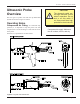
iQ Series, Ultrasonic Hand Held Systems User’s Manual
Dukane Manual Part No. 403-577-01
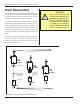
Stack Assembly
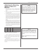
Attaching a Replaceable
Tip to a Horn
1. Inspect all horn and tip surfaces for stress cracks,
chips, or gouges. Any of these irregularities will affect
operation and could lead to further equipment damage.
Contact the Dukane Ultrasonics Tooling Department
concerning damaged horn components.
2. Apply an extremely thin layer of a high temperature,
high pressure silicon grease to the back surface that
mates with the horn. The grease will allow both
surfaces to intimately mate and become acoustically
transparent which improves the energy transfer. Do
not apply any grease to the threads. We recommend
Dow–Corning #4 (or #111 as an alternate). A small
packet of Dow–Corning #4 is supplied with the system.
If you cannot use a silicon–based grease in your facil-
ity, a petroleum–based grease may be used. However, it
is likely to leave carbonaceous deposits on the surface,
and require more frequent joint maintenance. Failure
to follow these instructions, may result in the mating
surfaces bonding and difculty removing the tip from
the horn.
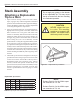
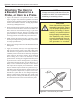
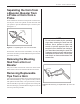
3. Thread the tip into the horn and tighten to the torque
specications below using an open end wrench of the
correct size to t the wrench ats of the tip. This is
illustrated in Figure 6-4. If necessary, use a spanner
wrench (on horns with spanner wrench holes) or an
open end wrench (on horns with wrench ats) to keep
the horn from turning in your hand. A canvas strap
wrench is permissible if it does not gouge or scratch
the horn.
Tighten
Figure 6–4 Replaceable Tip Installation
CAUTION
NEVER clamp the horn
in a vise. The resulting
scratches or gouges in the
surface are stress risers
which may result in cracks.
NOTE
Dukane Part No. for the 20kHz span-
ner wrenches is 721–68.
Dukane Part No. for the 40kHz span-
ner wrenches is 721–44.
NOTE
Do not apply any grease to the threads
of the replaceable tip. This may cause
the tip to loosen from the horn resulting
in inconsistent operation.
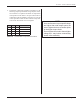
inch-lb ft-lb N-m Size
360 30 40.7 1/2” x 20 tpi tip threads
336 28 38 3/8” x 24 tpi tip threads
300 25 33.9 5/16” x 24 tpi tip threads
240 20 27.1 1/4” x 28 tpi tip threads
Replaceable Tips to Horn
Table 6-I Tip Torque Unit Conversions