Intelligent Assembly Solutions iQ Series ULTRASONIC HAND HELD SYSTEMS HP AUTOMATED HAND PROBE PRESS User’s Manual Dukane Part No. 403 – 577– 01 Dukane Intelligent Assembly Solutions • 2900 Dukane Drive St. • Charles, Illinois 60174 USA • TEL (630) 797- 4900 • FAX (630) 797- 4949 ISO 9001:2000 Products are manufactured in ISO registered facilities. www.dukane.
iQ Series, Ultrasonic Hand Held Systems User’s Manual Copyright © 2009 Notice of Rights: All rights reserved. No part of this manual including the interior design, cover design and icons may be reproduced, transmitted or utilized in any form or by any means, electronic, mechanical, photocopying, recording, or by any information storage and retrieval system, without written permission from the manufacturer.
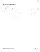
Revision History Revision Number Revision Summary - 00 - 01 Original release. Add 20kHz and 30kHz models. Update Pop-up Fault Status Screens. Add Trigger by Power feature. Add Options section. Dukane Manual Part No.
iQ Series, Ultrasonic Hand Held Systems User’s Manual This page intentionally left blank Page iv Dukane Manual Part No.
Contents Section 1- Introduction . . . . . . . . . . . . . . . . . . . . . . . . 1 Section 2- Health and Safety . . . . . . . . . . . . . . . . . . . 5 Section 3- Installation . . . . . . . . . . . . . . . . . . . . . . . . . 9 Unpacking . . . . . . . . . . . . . . . . . . . . . . . . . . . 11 Placing . . . . . . . . . . . . . . . . . . . . . . . . . . . . . . 11 RFI Grounding . . . . . . . . . . . . . . . . . . . . . . .
iQ Series, Ultrasonic Hand Held Systems User’s Manual This page intentionally left blank Page vi Dukane Manual Part No.
Section 1 – Introduction SECTION 1 Introduction General User Information . . . . . . . . . . . . . . . . . . . 3 Read The Manual First. . . . . . . . . . . . . . . . . . . . . . 3 Notes, Cautions and Warnings. . . . . . . . . . . . . . . . . . 3 Drawings and Tables. . . . . . . . . . . . . . . . . . . . . . . 3 System Overview. . . . . . . . . . . . . . . . . . . . . . . 4 Key Features . . . . . .
iQ Series, Ultrasonic Hand Held Systems User’s Manual This page intentionally left blank Page Dukane Manual Part No.
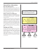
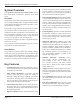
Section 1 – Introduction General User Information Read This Manual First Before operating your ultrasonic system, read this User’s Manual to become familiar with the equipment. This will ensure correct and safe operation. The manual is organized to allow you to learn how to safely operate this generator. The examples given are chosen for their simplicity to illustrate basic operation concepts. Notes, Cautions and Warnings NOTE Note statements provide additional information or highlight procedures.
iQ Series, Ultrasonic Hand Held Systems User’s Manual System Overview Your iQ Series Ultrasonic Hand Held System has two basic components: an ultrasonic generator, and a hand probe. Generator acoustic stack (horn, booster, transducer) and adjusts the generator output frequency to match it. This is done for every weld cycle and eliminates the need to manually tune the generator. • Line Voltage Regulation automatically maintains constant amplitude regardless of line voltage deviation.
Section 2 – Health & Safety SECTION 2 Health and Safety General Considerations . . . . . . . . . . . . . . . . . . . . . . . . . . . . . . . 7 Plastics Health Notice . . . . . . . . . . . . . . . . . . . . . . . . . . . . . . . . 7 Electrical Safety . . . . . . . . . . . . . . . . . . . . . . . . . . . . . . . . . . . . . 8 Dukane Manual Part No.
iQ Series, Ultrasonic Hand Held Systems User’s Manual This page intentionally left blank Page Dukane Manual Part No.
Section 2 – Health & Safety General Considerations Please observe these health and safety recommendations for safe, efficient, and injury-free operation of your equipment. In this manual, the term system refers to a complete group of components associated with the welding of plastic or metal parts, also known as an ultrasonic assembly system.
iQ Series, Ultrasonic Hand Held Systems User’s Manual Electrical Safety Domestic Power Grounding For safety, the power cords used on this product have a three-wire, grounding-type power cord. Figures 2-1 and 22 illustrate the appropriate electrical outlet to use with the power cords included with 100-120 volt and 200-240 volt systems respectively. This information applies to systems shipped to North America or Japan.
Section 3 – Installation SECTION 3 Installation Unpacking . . . . . . . . . . . . . . . . . . . . . . . . . . . . . . . . . . . . . . .11 Placing . . . . . . . . . . . . . . . . . . . . . . . . . . . . . . . . . . . . . . . . . 11 RFI Grounding . . . . . . . . . . . . . . . . . . . . . . . . . . . . . . . . . . . 11 Connnecting Cables . . . . . . . . . . . . . . . . . . . . . . . . . . . . . . . 12 System Outputs Connector . . . . . . . . . . . . . . . . . . . . . . . . . . . .
iQ Series, Ultrasonic Hand Held Systems User’s Manual This page intentionally left blank Page 10 Dukane Manual Part No.
Section 3 – Installation Unpacking Carefully open your shipping container, and make sure it contains the items shown on the shipping documents. Inspect all items, and report any missing items or damage immediately. Placing Make certain generator placement and cable routing do not interfere with normal operation. Maintain easy access to your equipment. The operator should have unobstructed access to cables and wiring.
iQ Series, Ultrasonic Hand Held Systems User’s Manual Connecting Cables - Quick Start Guide NOTE AC Power Inlet Complete the basic connections as shown below: Depending on your generator model, line voltage required for the generator is either 100-120 VAC at 50/60 Hertz or 200-240 VAC at 50/60 Hertz. The unit has a power switch, and is powered ON whenever the AC line power is live and the switch is in the ON position as shown in Figure 3-2 below.
Section 3 – Installation Power Cords 200/240 Volt Systems The IEC AC power inlet connector mounted on the rear panel requires a properly configured IEC compliant power cord. The 200/240 AC power cords supplied with the generators are matched to the ultrasonic output power rating and the continent of specified use. See Table 3-I.
iQ Series, Ultrasonic Hand Held Systems User’s Manual System Outputs (Optional Connections) The OUTPUTS connector is a four-position wire receptacle-type terminal block. If needed, it can provide the operator with basic system welding status. Everything connected to the OUTPUTS connector is customersupplied. Typically indicator lights or sound modules are powered by these output signals. (The lights or sound modules can be mounted on widely available Stack Light assemblies.
Section 4 – Controls and Connections SECTION 4 Controls Front Panel Overview . . . . . . . . . . . . . . . . . . . . . . . . . . . . . . . 17 Start-Up Sequence . . . . . . . . . . . . . . . . . . . . . . . . . . . . . . . . . 19 LCD Display Overview . . . . . . . . . . . . . . . . . . . . . . . . . . . . . . 20 Dukane Manual Part No.
iQ Series, Ultrasonic Hand Held Systems User’s Manual This page intentionally left blank Page 16 Dukane Manual Part No.
Section 4 – Controls and Connections Front Panel Overview This section gives an overview of the front panel functions: powering the generator on/off; monitoring the process with the display; and, programming with the control keys. Power Switch LCD Display Control Keys Figure 4-1 Front Panel Power Switch/Circuit Breaker The power switch/circuit breaker has a rocker-style actuator switch that will activate or deactivate the AC power to the system.
iQ Series, Ultrasonic Hand Held Systems User’s Manual Control Keys Continued AMP Set the ultrasound amplitude output level in the range of 20 to 100%. Typically amplitude is set to 100%. TIME Use this key to select time as the primary method of welding. Set the weld time (seconds). ENERGY Use this key to select energy as the primary method of welding. Set the weld energy (joules). HOLD Hold is a time period beginning after the weld portion of the cycle is complete.
Section 4 – Controls and Connections Start-up Sequence Push ON After all connections have been completed. Push OFF 1. Push the Power Switch to ON (Figure 4-2). The generator performs a self-diagnostics sequence. 2. The Power-up screen appears briefly - Figure 4-3. 3. The next screen is an Operate screen ready for a new weld to be done. The display shows: Figure 4-2 Power Switch Software version MB FPGA version DUKANE iQ Hand Probe Setup #1 xxxxxxxxx xxxxxxx http://www.dukcorp.
iQ Series, Ultrasonic Hand Held Systems User’s Manual LCD Display Overview There are two basic kinds of screen displays: Operate screens, and In Cycle screens. An Operate screen tells the operator what happened in the last weld cycle. Data from last weld cycle. Setup number. Manual Weld Weld Mode Manual, Time, or Energy Weld Time 0.500 S Weld Energy 18 J * #2 Asterisk indicates setup is modified but not stored in memory.
Section 5 - Process Control Settings SECTION 5 Process Control Settings Select the Welding Mode . . . . . . . . . . . . . . . . . . . . . . . . . . . . . 23 Navigating Through the Modes . . . . . . . . . . . . . . . . . . . . . 24-25 Hold . . . . . . . . . . . . . . . . . . . . . . . . . . . . . . . . . . . . . . . . . . . . 26 Amplitude Adjustment . . . . . . . . . . . . . . . . . . . . . . . . . . . . . . . 26 System Information, Hardware Settings, Advanced Settings . 27 Setup Maintenance . . . . . . .
iQ Series, Ultrasonic Hand Held Systems User’s Manual This page intentionally left blank Page 22 Dukane Manual Part No.
Section 5 - Process Control Settings Process Controller Settings This section of the manual helps the reader become familiar with the operating modes, and illustrates some typical programming steps. There are three welding modes available. These correspond to the three ways in which the welder can be used: Manual, Time, and Energy. Select the Welding Mode Manual - In MANUAL mode the operator controls the weld cycle.
iQ Series, Ultrasonic Hand Held Systems User’s Manual Navigating Through the Modes When the generator is first powered up, the default operating mode is Manual, and Manual Weld is shown at the top of the display as shown in Figure 5-1. Navigate to Time Mode 1. Follow the sequence shown in the figures to the right to navigate from Manual mode to Time mode. Manual Weld Weld Time 0.000 S Weld Energy 0 J #2 Figure 5-1 Manual Weld Mode TIME key In Manual mode, press the TIME key (Figure 5-2). 2. 3.
Section 5 - Process Control Settings Navigate to Energy Mode 1. Weld by Time Follow the sequence shown in the figures to the right to navigate from Time mode to Energy mode. Weld Time 0.500 S Weld Energy 00 J #2 Figure 5-5 Time Weld Mode ENERGY key Weld By Time In Time mode (Figure 5-5), press the ENERGY key, and the screen as shown in Figure 5-6 appears. Weld By Energy OFF Enter Changes Mode Figure 5-6 Navigate to Energy Mode - 1 Weld ENTER key 2.
iQ Series, Ultrasonic Hand Held Systems User’s Manual Hold HOLD is used more often with Time or Energy modes, but it can be used with the Manual mode. It is a period of time that can be set to follow release of the probe’s trigger switch. During HOLD the operator typically applies pressure to the part being welded. Next, the operator hears an audible alarm that serves as a reminder that HOLD has finished, and the probe can be lifted.
Section 5 - Process Control Settings System Information, Hardware Settings, Advanced Settings When the INFO key is pressed the display looks like Figure 5-11: Using the + - keys, move the pointer to indicate: System Information, Hardware Settings, or Advanced Settings Press ENTER to make the selection. 1. System Information Manufacturer’s information is shown including the manufacturer’s name, the name of the system (iQ 20kHz Hand Probe) and the software identification.
iQ Series, Ultrasonic Hand Held Systems User’s Manual 3. Advanced Settings Continued After Advanced Settings is selected, a warning screen is displayed as shown in Figure 5-13. Adjusting these settings may affect the operation of your unit. Before you change a setting, please check with Dukane personnel for their recommendations.
Section 5 - Process Control Settings Advanced Settings Continued Trigger by Power For an explanation of Trigger by Power and the three settings that are connected with it, please refer to Application Note 506 found on our website at: http://www.dukane.com/us/DL_ApplData.
iQ Series, Ultrasonic Hand Held Systems User’s Manual Setup Maintenance Setup Maintenance Introduction The screens available in Setup Maintenance allow the operator to Load, Store, or Delete generator weld setups. As many as eight (8) setups can be loaded and stored for your convenience. Load Setup # 1 Store Delete EMPTY Figure 5-18 Setup Maintenance - 1 Navigating 1. 2. 3. 4. When the SETUP key is pressed for the first time, the display looks like Figure 5-18.
Section 5 - Process Control Settings Setup Maintenance Continued Weld by Time Saving the Current Setup Try using your navigation skills on this example: 1. Follow instructions on Page 24 to set the mode to Weld by Time. Set the time to 1.520 seconds. See Figure 5-23. 2. Press SETUP and then press the + key until you get an Empty Setup Maintenance screen. See Figure 5-24. 3. 4. Weld Time 1.
iQ Series, Ultrasonic Hand Held Systems User’s Manual This page intentionally left blank Page Dukane Manual Part No.
Section 6 – Probes and Probe Stacks SECTION 6 Probes and Probe Stacks Ultrasonic Probe Overview............................35 Theory of Operation.............................................36 Probe Configuration.............................................36 Ultrasonic Horn....................................................37 Booster.................................................................37 Stack Assembly.............................................38 Installing Replaceable Tips...............
iQ Series, Ultrasonic Hand Held Systems User’s Manual This page intentionally left blank Page Dukane Manual Part No.
Section 6 – Probes and Probe Stacks Ultrasonic Probe Overview The two types of probes used with the iQ Hand Held Systems are shown in Figure 6-1 below. Operating Notes Compressed Air Fitting - In continuous duty CAUTION The ultrasonic cable carries high electrical current when in operation. Do not nick or cut this cable. If cut, there would be a high potential for electric shock! NOTE operation, it is important to keep the probe cool with compressed air.
iQ Series, Ultrasonic Hand Held Systems User’s Manual Theory of Operation Plastic welding is the most common application of ultrasonic assembly. To perform ultrasonic plastic welding, the vibrating tip is brought into contact with one of the work pieces. Pressure is applied and ultrasonic energy travels through the material generating frictional heat at the contact point of the two parts.
Section 6 – Probes and Probe Stacks Ultrasonic Horn The horn transfers the ultrasonic mechanical vibrations (originating at the transducer in the probe housing) to the plastic parts through direct physical contact. The horn is precision machined and designed to vibrate at either 20kHz, 30kHz, 40kHz, 50kHz or 70kHz. The tuning is accomplished using electronic frequency measurement. Inherent variations in material composition prevent tuning by dimensional machining alone.
iQ Series, Ultrasonic Hand Held Systems User’s Manual Stack Assembly Attaching a Replaceable Tip to a Horn 1. Inspect all horn and tip surfaces for stress cracks, chips, or gouges. Any of these irregularities will affect operation and could lead to further equipment damage. Contact the Dukane Ultrasonics Tooling Department concerning damaged horn components. 2. Apply an extremely thin layer of a high temperature, high pressure silicon grease to the back surface that mates with the horn.
Section 6 – Probes and Probe Stacks Attaching the Mounting Stud to a Horn or a Booster 1. Inspect the stud for cracks or damaged threads. Replace the stud if it is cracked or otherwise damaged. 2. Remove any foreign matter from the threaded stud and the mating hole. NOTE Do not apply any grease to the stud threads or the tapped hole. This may cause the stud to loosen. If the stud wanders within the joint, it can vibrate, resulting in excessive heat. In some cases, this can melt the tooling material. 3.
iQ Series, Ultrasonic Hand Held Systems User’s Manual Attaching The Horn to a Booster, Booster to a Probe, or Horn to a Probe 1. Inspect all surfaces to be joined for stress cracks, chips, or gouges. Any of these irregularities will affect operation and could lead to further equipment damage. Contact the Dukane Ultrasonic Tooling Department concerning a damaged booster. 2. Ensure that the mating surfaces of the two components are clean and smooth.
Section 6 – Probes and Probe Stacks 6. Thread the components together and tighten to the following torque specifications using only the correct size wrenches. Use spanner wrenches on components with spanner wrench holes or an open end wrench on components with wrench flats. See Figure 6–5 for the correct procedure. Refer to Table 6-III for torque unit conversions. Be careful not to overtighten. In-lb Ft-lb N-m 540 45 420 35 47.5 20 kHz stack 216 18 24.4 30 kHz stack 216 18 24.
iQ Series, Ultrasonic Hand Held Systems User’s Manual Stack Disassembly Stack disassembly is required when changing the booster or horn, or for a thorough inspection of all stack components. In mounted systems, always remove the stack from its mounting to disassemble the stack components. To establish a maintenance schedule, inspect the mating surfaces after the first 200–400 hours of operation. If they require cleaning, halve the time between inspections.
Section 6 – Probes and Probe Stacks Separating the Horn from a Booster, Booster from a Probe or Horn from a Probe On all transducers and horns with spanner wrench holes, use only the correct size spanner wrench that came with your system to provide sufficient torque to loosen a joint. See Figure 6–7. Loosen NOTE Figure 6–7 Separating the Horn from the Booster On boosters and horns with wrench flats, use only the correct size wrench to provide sufficient torque to loosen a joint when necessary.
iQ Series, Ultrasonic Hand Held Systems User’s Manual Booster Notes How to Tell the Booster Input End from the Output 1. The depth of the threaded hole on the output end is always deeper than the threaded hole on the input end. 2. On an amplifying booster (gain > 1.0), the larger diameter end is the input end. On a reducing booster (gain < 1.0) the larger diameter end is the output end. On a neutral acting booster the diameters are equal. 3.
Section 7 – Troubleshooting SECTION 7 Troubleshooting No Ultrasonic Output...................................... 47 System Power Output Level..........................47 Welding Problems.......................................... 48 Pop-up Fault Status Screens.................. 49-50 Dukane Manual Part No.
iQ Series, Ultrasonic Hand Held Systems User’s Manual This page intentionally left blank Page Dukane Manual Part No.
Section 7 – Troubleshooting No Ultrasonic Output Probe Make sure that the hand probe cable is connected to the generator connector (HAND PROBE) and secured to the rear panel. Also, make sure the hand probe stack is properly assembled. System Power Output Level Overload When an overload occurs, it will automatically reset when the next ultrasound activation signal begins. If the condition persists: Turn the generator OFF and: 1. Check the system. Change the hand probe to one that is known to be good.
iQ Series, Ultrasonic Hand Held Systems User’s Manual Welding Problems Weak Welds Weak welds, or underwelding, is caused by insufficient energy being transmitted to the part. You can increase the weld pressure, increase the weld duration (Time or Energy) or change to a higher gain booster to increase the amplitude to increase the energy delivered to the weld. NOTE Primary factors in achieving consistent, quality welds - especially when using hand held probes - are the skill and training of the operator.
Section 7 – Troubleshooting Pop-up Fault Status Screens Generator Fault Status Screens - Manual Mode Status Text Displayed Generator Fault Average Overload Generator Fault Peak Overload Generator Fault Frequency Lock Lost Generator Fault System Status or Fault Explanation An Average Overload fault tripped. Output power exceeded rated wattage. Lower the welding pressure or amplitude. Fault will reset when next weld cycle starts. A Positive Peak Overload fault tripped.
iQ Series, Ultrasonic Hand Held Systems User’s Manual Process Fault Status Screens - Time and Energy Modes Status Text Displayed Latch On Fault ENABLED Process Fault Set Weld Time Not Reached Process Fault Set Weld Time Not Reached Enter Clears Fault Process Fault Set Weld Energy Not Reached System Status or Fault Explanation Latch On Fault DISABLED Process Fault Set Weld Energy Not Reached Set Weld Time Not Reached, or Set Weld Energy Not Reached - appears if the weld ends before the set time or e
Section 8 – Options SECTION 8 Options iQ Hand Probe Buzzer Kit.............................. 53 iQ Hand Probe Foot Switch Kit......................53 Dukane Manual Part No.
iQ Series, Ultrasonic Hand Held Systems User’s Manual This page intentionally left blank Page 52 Dukane Manual Part No.
Section 8 – Options iQ Hand Probe Options Buzzer Kit (Part No. 438-971) In some noisy environments the built-in buzzer can not easily be heard. This buzzer kit is designed for those conditions, and it suits the customer that prefers not to provide their own buzzer (using the status outputs of the generator). The kit adds a 100dB buzzer inside the generator. Foot Switch Kit (Part No. 438-976) This kit allows the customer to add their own external foot switch to replace the trigger on the hand probe.
iQ Series, Ultrasonic Hand Held Systems User’s Manual This page intentionally left blank Page 54 Dukane Manual Part No.
Section 9 – Specifications SECTION 9 Specifications Generator Outline Drawing . . . . . . . . . . . . . . . . . . . . . . . . . . . 57 Probes Outline Drawings . . . . . . . . . . . . . . . . . . . . . . . . . . . . . 58 Weights . . . . . . . . . . . . . . . . . . . . . . . . . . . . . . . . . . . . . . . . . . 59 Operating Environment . . . . . . . . . . . . . . . . . . . . . . . . . . . . . . 59 AC Power Requirements . . . . . . . . . . . . . . . . . . . . . . . . . . . . .
iQ Series, Ultrasonic Hand Held Systems User’s Manual This page intentionally left blank Page 56 Dukane Manual Part No.
Section 9 – Specifications ALLOW 5" (125 mm) BEHIND UNIT FOR CABLE CONNECTIONS 12.41 [315.2] 10.00 [254] 3.95 [100.3] 3.51 [89.2] IN [mm] Figure 9-1 Generator Outline Drawing Dukane Manual Part No.
iQ Series, Ultrasonic Hand Held Systems User’s Manual B C A 2.59 in (66 mm) 1.25 in (32 mm) Diameter Air fitting for cooling .25 in O.D. tubing Soft grip handle Standard single connector for iQ generator A B Air fitting for cooling .25 in O.D. tubing C 1.25 in (31.75 mm) Diameter D Standard cable 9 ft (3 m) 1.
Section 9 – Specifications Weights Generator: 12 pounds (5.44 kg) Probes: Please see the table on the previous page. Shipping: Add 5 pounds (2.27 kg) to unit weight for packing materials. Operating Environment Operate the equipment within these guidelines: Temperature: 40°F to 100°F (+5°C to +38°C) Air Particulates: Keep the equipment dry. Minimize exposure to moisture, dust, dirt, smoke and mold.
iQ Series, Ultrasonic Hand Held Systems User’s Manual AC Power Requirements Overload Power Rating (Watts) System Model Number Generator Model Number Probe Part Number 20kHz HP 2.61-P 20HP060-1E 41PG20S 100-120 VAC, 50/60 Hz @ 9.0 Amps 20kHz HP 2.61-H 20HP060-1E 41HP20S 100-120 VAC, 50/60 Hz @ 9.0 Amps 20kHz HP 2.62-P 20HP060-2E 41PG20S 200-240 VAC, 50/60 Hz @ 4.5 Amps 20kHz HP 2.62-H 20HP060-2E 41HP20S 200-240 VAC, 50/60 Hz @ 4.5 Amps 30kHz HP 3.
Section 9 – Specifications Regulatory Agency Compliance FCC The generator complies with the following Federal Communications Commission regulations. • The limits for FCC measurement procedure MP-5, “Methods of Measurement of Radio Noise Emissions from ISM Equipment”, pursuant to FCC Title 47 Part 18 for Ultrasonic Equipment.
iQ Series, Ultrasonic Hand Held Systems User’s Manual This page intentionally left blank Page 62 Dukane Manual Part No.
Section 10 – I/O Interface SECTION 10 Outputs Interface Outputs Connection Example . . . . . . . . . . . . . . . . . . . . . . . . . 65 Dukane Manual Part No.
iQ Series, Ultrasonic Hand Held Systems User’s Manual This page intentionally left blank Page 64 Dukane Manual Part No.
Section 10 – I/O Interface iQ Hand Probe Generator Rear Panel Detail HAND PROBE OUTPUTS 0V 1 2 3 Provided by Customer NOTE 0V (Output Common) is connected to Chassis Ground (Earth). Power Supply + 30 VDC Maximum To OUTPUTS: 1, 2, or 3 + 24 V X1 + _ X2 0V Status Indicator or Audible Alarm (333mA maximum) Figure 10-1 OUTPUTS Connection Example Dukane Manual Part No.
iQ Series, Ultrasonic Hand Held Systems User’s Manual This page intentionally left blank Page 66 Dukane Manual Part No.
Section 11 – Contacting Dukane SECTION 11 Contacting Dukane Dukane Manual Part No.
iQ Series, Ultrasonic Hand Held Systems User’s Manual This page intentionally left blank Page 68 Dukane Manual Part No.
Section 11 – Contacting Dukane Contacting Dukane Identify Equipment When contacting Dukane about a service–related problem, be prepared to give the following information: • Model number, line voltage and serial number • Fault/error indicators from the LCD display • Software version (Press INFO. With pointer at System Information, press ENTER to get this data.
iQ Series, Ultrasonic Hand Held Systems User’s Manual This page intentionally left blank Page 70 Dukane Manual Part No.
Appendices APPENDICES List of Figures . . . . . . . . . . . . . . . . . . . . . . . . . . . . . . . . . . . . . 73 List of Tables . . . . . . . . . . . . . . . . . . . . . . . . . . . . . . . . . . . . . . 74 Dukane Manual Part No.
iQ Series, Ultrasonic Hand Held Systems User’s Manual This page intentionally left blank Page 72 Dukane Manual Part No.
Appendices List of Figures No. Description Page 2-1 Example of 125 Volt, Grounded, 3-prong Plug and Receptacle.......................................8 2-2 Example of 250 Volt, Grounded, 3-prong Plug and Receptacle.......................................8 2-3 International 220/240V Grounding...................................................................................8 3-1 Generator Detail - Rear Views.......................................................................................
iQ Series, Ultrasonic Hand Held Systems User’s Manual List of Figures continued 5-18 Setup Maintenance - 1...................................................................................................30 5-18A Pop-up Load Defaults?...................................................................................................30 5-19 Setup Maintenance - 2...................................................................................................30 5-20 Setup Maintenance - 3............
Dukane ISO ISO CERTIFICATION Dukane chose to become ISO 9001:2000 certified in order to demonstrate to our customers our continuing commitment to being a quality vendor. By passing its audit, Dukane can assure you that we have in place a well–defined and systematic approach to quality design, manufacturing, delivery and service. This certificate reinforces Dukane's status as a quality vendor of technology and products.
Please refer to our website at: www.dukane.com/us/sales/intsales.htm to locate your local representative. iQ Series, Ultrasonic Hand Held Systems User's Manual Part No. 403 – 577– 01 www.dukane.com/us Printed in the United States of America Dukane Intelligent Assembly Solutions • 2900 Dukane Drive St.