
Programming instructions


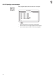


–
Enter the code number of the required receiver element on the
decimal keypad.
The abbreviated designations in the wiring diagram are used as
code numbers (see following table).
–
The display shows the wiring-diagram designation and the switch
status of the selected receiver element (e.g. "+S17").
The display changes to reflect any change in the switch status of
the receiver element.
The switch status "-" means:
contact switch = contact open
proximity switch = metal in front of the switch
reflecting light barrier = no reflection
–
Adjust the receiver element until the display shows the required
switch status.
–
Press the F1 function key to leave the test program.
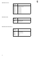
Receiver elements
main distributor
receiver function
element
S01 foot switch 1 folding table vacuum on
S02 foot switch 2 folding lip lower retraction off
S03 foot switch 3 folding lip swivel on
S04 foot switch 4 start dart
S05 Ref_X axle_1
S07 Ref_Y axle_1
S09 folding table in starting position
S10 folding table retracted
S11 folding lip extended below
S12 folding lip retracted below
S13 slide-plate catch
S14 rail down
S15 flap down
S16 flap central
S17 flap not raised
S18 vertical cutter on
S19 vertical cutter off
S20 waist-point code 1
S21 waist-point code 2
S22 waist-point code 3
S23 waist-point code 4
S24 thread monitor
S25 folding table engaged
S26 compressed-air monitor
S27 seam-end light barrier
S28 folding-table stop button
4
41