Contents page: Part 4: DAC class 743-115 programming instructions Program version 743-115-1012 1. General . . . . . . . . . . . . . . . . . . . . . . . . . . . . . . . . . . . . . . . . . . . . . . . . . 3 2. Operating terminal . . . . . . . . . . . . . . . . . . . . . . . . . . . . . . . . . . . . . . . . . . 4 3. 3.1 3.1.1 3.1.2 3.2 Memory card . . . . . . . . . . . . . . . Saving and loading programs . . . . . . Transferring data to the memory card .
Contents page: 7. 7.1 Error messages . . . . . . . . . . . . . . . . . . . . . . . . . . . . . . . . . . . . . . . . . . . Controller error messages . . . . . . . . . . . . . . . . . . . . . . . . . . . . . . . . . . . . . . 49 49 A. A.1 A.2 A.3 A.4 A.5 A.5.1 A.5.2 A.6 A.6.1 A.6.2 A.6.3 A.6.4 Appendix . . . . . . . . . . . . . . . . . . . . . . . . . . . . . . . . Safety messages . . . . . . . . . . . . . . . . . . . . . . . . . . . . Summary of seam types . . . . . . . . . . . . . . . . . . . . . . .
1. General This manual contains important information on the safe, correct and economical use of the new-generation "DAC" (Dürkopp Adler Control) controller. Screen images in this brief description The symbol display on the various screens depends on the sewing machine’s equipment and settings. The screen images illustrated in this brief description may therefore not always correspond exactly with the screens appearing in the controller display.
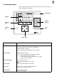
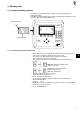
2. Operating terminal Data is input and output via an operating terminal with an LCD display and a multipurpose keyboard. Stop button 743-115 04 display 03 160 170 180 Mustermann___ 48 46 50 52 54 1 GP Σ : 0099 01 98 2 PP 3 PS 4 SP decimal keypad function keys escape key enter key cursor keys 4 Key/key group function Function keys Call the sewing-program parameter screens (from the main screen). Call test programs (while the logo is displayed). Switch functions on and off.
3. Memory card 3.1 Saving and loading programs The memory card (RAM card) is a long-term storage medium for sewing programs. It enables sewing-program data, seams and machine parameters to be transferred to other sewing machines. write protection STOP Start lettering panel ESC DURKOPP ADLER AG 3.1.1 Transferring data to the memory card – – When the main screen is displayed insert the memory card in the side of the controller in the direction of the arrow.
3.1.2 Transferring data from the memory card to the controller CAUTION: The sewing machine must not be switched off during the transfer of data to the controller. – – When the main screen is displayed insert the memory card in the side of the controller in the direction of the arrow. The panel with lettering must be towards the operator. The controller switches to save mode.
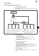
4. User interface 4.1 Sewing and test programs: menu structure The user interface exclusively employs internationally intelligible symbols. The individual parameters and setting and test programs are arranged in various groups. turn on main switch main screen Stop 4 Sewing-program parameter menus Setting and test programs Calling sewing programs – Turn on the main switch. The controller is initialised. The DÜRKOPP-ADLER logo briefly appears in the display. – The display switches to the main screen.
4.2 Changing parameter values The parameter values are changed in the individual parameter screens. – – – – Select the required parameter with cursor keys ”!" or """. The symbol of the selected parameter appears in reverse video. Press Enter. The settings window appears with the current values or to enable values to be entered. Change the parameters as described under 1 to 4. Press Enter. The new parameter settings are saved.
5. Sewing programs The 743-115 can run 99 different sewing programs, 92 of which are freely programmable. 50 independent memory locations are available for sewing program sequences. Each individual memory location can consist of up to 2 sewing programs in any order. 5.1 Calling the sewing-program parameter screens You can switch from the main screen to the various sewing-program parameter screens with function keys F1 to F3.
5.2 Starting the machine program – – – – – 10 Turn on the main switch. The controller is initialised. The DÜRKOPP-ADLER logo briefly appears in the display. If one of the function keys F1 to F4 is pressed while the logo is being displayed, the display switches to the corresponding group of setting or test programs. The material guide-rail executes its reference travel. The display switches to the main screen.
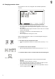
5.3 Main screen The main screen displays the seam image, sewing program and program sequence, program name and the dart lengths with their allocated sizes. 743-115 04 03 160 170 180 Mustermann___ 46 50 52 48 98 54 1 GP Σ : 0099 01 2 PP 3 PS 4 SP Seam image The upper part of the main screen displays the contours of the selected seam image. Below the seam image an information line appears with the following information: > > Program number and program sequence (see also section 5.
Piece counter The current piece-counter reading is displayed on the right (e.g. "Σ : 0099"). The piece counter shows the number of pieces completed since the last time the counter was reset. The piece counter is reset under "Global parameters" (function key F1). Dart-length table The table of dart lengths with their allocated sizes displays the dart length currently set in reverse video in the middle of the corresponding window. The minimum and maximum dart lengths are exceptions.
5.3.1 Main-screen messages "Rail change required" message If a sewing-program change necessitates a guide-rail change, a warning message automatically appears on the screen and an acoustic signal sounds. 743-115 04 160 170 180 03 Mustermann___ 46 50 52 48 – Σ : 0099 98 54 Code 32: GP 01 PP ● ❍❍ ❍❍❍ PS SP Press Enter. The guide-rail change menu is called. or – Press the Escape button. The message disappears.
"Thread break" message If a thread break occurs during sewing, a message to that effect appears at the end of the sewing cycle. When a thread-change is carried out, the required steps are shown on the screen. The thread-break message can be cleared with the ”ESC” key. – Press Enter. The instruction "raise protective hood" appears. – – Raise the protective hood. The instruction "open slide-plate lock" appears. – – 14 – Open the slide-plate lock and push the slide plate fully to the right.
"Cannot be sewn" message After a change of sewing program or material-guide rail or the amendment of a sewing program a plausibility check is automatically carried out by the controller. If the check identifies an error, the following message appears on the main screen. The sewing machine is blocked for further operation. – Check the sewing program. – Press Enter. The message disappears. – Check the sewing program and rail code.
"Rail change required" message This menu prepares for the rail change. 743-115 04 03 160 170 180 Mustermann___ 46 50 52 48 – 98 54 1 2 3 PP GP Σ : 0099 01 PS 4 SP Press key 1 on the decimal keypad. The rail moves to the left. The rail change menu is called. 743-115 04 160 170 180 03 Mustermann___ 46 50 52 48 – – Σ : 0099 98 54 Code 32: GP 01 PP ● ❍❍ ❍❍❍ PS SP Changing the material-guide rail. See Operating instructions, section 4.7. Press Enter.
"Change thread" message This menu prepares for a thread change. – Press key 2 on the decimal keypad. The material-guide rail moves to the left and the "change thread" screen appears. When a thread-change is carried out, the required steps are shown on the screen. – Press Enter. The instruction "raise protective hood" appears. 4 – Raise the protective hood. The instruction "open slide-plate lock" appears. – Open the slide-plate lock and push the slide plate fully to the right.
5.4 Global parameters ( GP) Global parameters are parameters that are valid for all sewing programs. Example: If the stacker is switched on, all pieces are deposited in the stacker. – – – – When the main screen is displayed press function key F1. The display switches to the global parameters screen. Select the required parameter with cursor keys ”!" or """. The symbol of the selected parameter appears in reverse video. Alter the selected parameter as described in section 4.2.
Sewing speed Entry: 100 to 4800 rpm Single step This parameter is used to test and adjust the sewing machine quickly. Sewing is halted at pre-set items. Processing can be halted at any individual step by pressing the Stop button. Entry: on/off ? ?? Test seam Entry: on/off – Select test seam with the Enter key. The prompt to enter the code number appears in the display. – Enter the code number "29801" on the decimal keypad. – Once the correct number has been entered the test seam can be switched on.
Rail code Entry: rail code in the X and Y directions The guide-rail co-ordinates are impressed on each rail. Tolerances when the rail bends may make it necessary to adjust these values (see Servicing instructions, section 3.3.7: adapting the rail code). indication of rail co-ordinates rail co-ordinates Procedure – When the main screen is displayed press function key F1. The display switches to the ”Global parameters” screen. – Select the "rail code" parameter with cursor keys – – – 20 "!" or """.
– – – – – Select the required co-ordinate point with cursor keys ”!" or """. The parameter symbol appears in reverse video. Press Enter. Enter value. Press Enter. The value entered is saved. Press key F1 to leave the menu.
5.5 Program parameters (PP) Parameters for programming the various sewing programs are arranged under this menu item. These parameters enable the seams and their associated additional functions to be freely programmed. PP: 01 743-115 I X – – – – – < > When the main screen is displayed press function key F2. The display switches to the sewing-program screen. The sewing program currently selected (e.g. "PP : 01") is displayed in the upper left display line.
Enter program name This parameter can be used to assign a program name to each sewing program. The program name must consist of a maximum of 16 letters. Example: "ROMLINKS" Seam type This parameter is used to enter the seam type. The required type is selected with the cursor keys.
Assign dart-length sizes This parameter is used to assign dart-length sizes. Up to 5 sizes can be entered for each dart length. Procedure – When the main screen is displayed press function key F2. The display switches to the ”sewing program” screen. – Select the "size assignment" parameter with cursor keys ”!" or """. The symbol of the selected parameter appears in reverse video. – Press Enter. The dart-length window appears.
Variable dart depth ON/OFF This parameter determines whether the same dart depths are set for all dart lengths when dart lengths are programmed or whether they can be programmed separately for each dart. Entry: on/off same dart depth for all dart lengths dart depth separately programmable for each dart length.
Program dart form This is where the dart-length co-ordinates are programmed. You are prompted to enter only the co-ordinates required for the seam type in question. Entry: select the dart length with the cursor keys. Procedure – When the main screen is displayed press function key F2. The display switches to the ”sewing program” screen. – Select the "dart depth" parameter with cursor keys ”!" or """. The parameter symbol appears in reverse video. – Press Enter. The dart-depth window appears.
Select fabric thickness thin fabric medium fabric thick fabric Rail code A sewing program can be assigned to a particular material-guide rail.
5.6 Program sequences ( PS ) Individual sewing programs or program sequences are grouped together under this menu item. A total of 50 independent program locations is available. A program sequence may consist of a maximum of two sewing programs in any order. 743-115 37. 38. 39. 40.
Turning the automatic sewing-program switch on and off If this function is on, then when one sewing program has been completed the controller automatically switches to the next sewing program in the sewing sequence. Pressing function key F4 turns off the automatic sewing-program switch. When the automatic switch is on, arrows appear in the display between the individual sewing programs of the sewing sequences.
6. Settings and test programs The machine software includes various machine-specific settings and test programs, as well as the well-known Multitest system. A terminal self-test checks the individual components of the operating terminal. 6.1 Calling the setting and test programs Once the sewing machine has been switched on, pressing function keys F1 to F4 switches to the various groups of setting and test programs.
6.2 Machine parameters ( STOP + ) The machine parameters describe the technical version of the sewing machine, as well as the machine settings and their correction values. CAUTION: Changing the machine settings generally requires mechanical conversion to be carried out. This part of the program is therefore accessible only after the code number "29801" has been entered. – ? ?? – – – – – During the display of the DÜRKOPP-ADLER logo press the "STOP" key, followed by function key F1.
Number of stitches The number of stitches for the individual regions of the dart or the side-seam is entered separately for the three different fabric thicknesses. The dart or side-seam is divided into different vectors.
– Select fabric thickness 1 - thin. fabric thickness 1 - thin fabric thickness 2 - medium fabric thickness 3 - thick – Select the vectors individually and enter the number of stitches. After entering all the stitch numbers for fabric thickness 1: – Select fabric thickness 2. – Select the vectors individually and enter the number of stitches. – Select fabric thickness 3. – Select the vectors individually and enter the number of stitches.
Stitch length The stitch length can be entered separately for individual regions of the dart or side seam and for the various fabric thicknesses. Entry: 0.1 to 2.5 [mm] 2 1 3 2 The dart/side seam is divided into different stitch-length regions.
– Select the stitch-length regions individually and enter the stitch length. After entering all three stitch lengths for fabric thickness 1: – Select fabric thickness 2. – Select the stitch-length regions individually and enter the stitch length. – Select fabric thickness 3. – Select the stitch-length regions individually and enter the stitch length.
Piece counter (overall piece counter) Entry: none, display only Reference correction CAUTION: The reference position is precisely adjusted in our works with a special gauge. Do not alter these values. reference position in the X direction e.g. = 12.0 reference position in the Y direction e.g. = 0.
6.3 Machine-specific setting and test programs ( + STOP ) The machine-specific test programs are used to adjust and test the individual machine components. – – – During the display of the DÜRKOPP-ADLER logo press the "Stop" key followed by function key F2. The display switches to the machine-specific test-program screen. Select the required test program with cursor keys ”!" or """. The symbol of the selected test program appears in reverse video. Press the Enter key to run the selected test program.
6.3.2 Sewing-foot setting This program is used to run the "sewing-foot setting" test. The test takes place in stages that are initiated individually by operating the foot pedal. The process can be terminated at any time by pressing the STOP key. – – – – – – – – Press the Enter key to run the test program. Operate the foot pedal. The guide rail descends. Operate the foot pedal. The sewing foot and fabric-thickness cylinders descend. Operate the foot pedal. The sewing foot is locked.
6.4 Multitest system ( STOP + ) The Multitest system consists of a number of programs for the rapid testing of receiver and transmitter elements. There is no need for any additional measuring devices. – – – During the display of the DÜRKOPP-ADLER logo press the "Stop" key and then the F3 function key. The display switches to the Multitest system screen. Select the required test program with cursor keys ”!" or """. The symbol of the selected test program appears in reverse video.
6.4.2 Testing working memory This program tests the microcomputer’s working memory (RAM). – – Press the Enter key to run the test program. The display shows the test result. display remark RAM OK RAM error working memory functioning perfectly error in the working memory Press the F1 function key to leave the test program. 6.4.3 Selecting receiver elements This program selects receiver elements. Input-Select S ? -- Input-Nr.
– – Enter the code number of the required receiver element on the decimal keypad. The abbreviated designations in the wiring diagram are used as code numbers (see following table). The display shows the wiring-diagram designation and the switch status of the selected receiver element (e.g. "+S17"). The display changes to reflect any change in the switch status of the receiver element.
CAN node 743-115-0 receiver element SC001 SC002 SC003 SC004 SC005 SC006 SC007 SC008 function light barrier fabric prompt upper-part catch rail code 1 rail code 2 rail code 3 rail code 4 rail code 5 rail code 6 CAN node stacker receiver element function SC101 SC102 smoother right smoother left receiver element function SC201 SC202 SC203 SC204 clamp strip left clamp strip right start 1 start 2 CAN node side-seam device -2 42
6.4.4 Testing the receiver elements This program tests the receiver elements. – – – – Press the Enter key to run the test program. Operate the receiver element to be tested. The display shows the wiring-diagram designation and switch status of the selected receiver element (e.g. "+S17"). The display changes to reflect any change in switch status or if a different receiver element is altered. An acoustic signal sounds to indicate a change in switch status.
6.4.5 Selecting the transmitter elements This program checks the function of the transmitter elements. Caution: danger of injury Do not reach into the machine while the transmitter elements are being function-tested. – – – – – – Press the Enter key to run the test program. Select distributor Y or YC. Enter the code number of the required transmitter element. The abbreviated designations in the wiring diagram are used as code numbers (see following table).
Main distributor outputs transmitter element function YC008 YC007 YC006 YC005 YC004 YC003 YC002 YC001 folding table vacuum vacuum-lift fabric sections extend folding table clear fluff lower fabric clamp swivel folding lip folding-lip stop forwards lower folding lip Y1 Y2 Y3 raise fabric-compression foot raise flap fabric stop and folding lip are up – lower them lower comb clamp lift rail lock fabric-compression foot fabric-thickness prompt increase thread tension cutter transport apply cutter clamp und
6.4.6 Testing the step drive This program tests the material-guide rail drive. Stepper-Test n Stepper-Motor : 1 Speed : 200 < left U/min right CAUTION: danger of breakage Do not allow the step drives to travel as far as the stop during the function test. – – – – – – – – – – 46 Press the Enter key to run the test program. Select the symbol for the motor with the cursor keys "!" or """. Motor 1 = X axle Motor 2 = Y axle. Press Enter.
6.4.7 Testing the sewing drive This program is used to test the needle positions and the various rpm stages of the sewing drive. – – – Press the Enter key to run the test program. Select the symbol of the required parameter with cursor keys ”!" or """. The selected symbol appears in reverse video. Adjust the parameter with cursor keys ”#" or "$".
6.4.8 Displaying error messages This program displays the last 10 error messages. MULTITEST error messages 01. 02. 03. 04. 05. 06. 07. 08. 09. 10. – – 48 -> -> -> -> -> -> -> -> -> -> Error 902/-8 Error 902/-8 Error 902/-8 Error 902/-8 Error 902/-8 Error 902/-8 Error 903/-22358 Error 903/-22358 Error 959/201 EXTERN STOP Press the Enter key to run the test program. The last 10 error messages appear in the display. Press the F1 function key to leave the program.
7. Error messages In the event of an error in the control system or in the machine program the display shows the corresponding error number. The following tables enable the cause of the error to be determined and help to rectify it. 7.
A. Appendix A.1 safety messages During operation the sewing machine is constantly interrogated by the controller about matters with safety implications. If any response is not satisfactory, a safety message appears in the display. Slide-plate catch The slide-plate catch has been opened. – Engage the slide plate. The message disappears. Protective hood not down The protective hood has been raised. – Lower the protective hood. The message disappears.
Sewing-length range exceeded Incorrect insertion position (side seam only) The side-seam insertion range is marked on the clamp strips with two red flags. – Turn the main switch off and on again. Upper part not engaged If the upper part of the machine has not engaged properly after being swivelled up or down, the message "upper part not engaged" appears. Sewing is blocked. – Engage the upper part. – Press Enter to clear the message. The sewing machine is ready for operation.
A.
A.3 Creating a seam program In these examples we explain how you can create your own program for a jacket-breast dart from one of the seven standard programs. Our sample program is based on a seam of deftyp 001: The following steps are explained: 1. selecting a seam type 2. copying a seam program 3. entering a program name 4. entering a program sequence. Procedure 1.
2. Copying a seam program – When the main screen is displayed press function key F2. The program-parameters screen appears. PP: 01 743-115 I X – – – – 3. > Select a parameter with cursor keys ”!" or """. The symbol of the selected parameter appears in reverse video. Press Enter. The seam program is copied. Enter a new seam-program number: Example: 99 Press Enter. The new seam program with the values of program "deftyp 001" is saved.
4. Entering a program sequence – When the main screen is displayed press function key F3. The "program-sequences" screen appears. – Use the cursor keys "#" or "$" to look for a free program location (example no. 50). Press Enter. Enter the program number. Example: program 99 Press the F1 function key. The "program-sequences" menu is closed.
A.4 Programming a seam – When the main screen is displayed press function key F2. The display switches to the sewing-program screen. PP: 01 743-115 I X – – – – – – – – – – – – – 56 < > Select the "equal/unequal dart depths" parameter with cursor keys "!" or """. The symbol of the selected parameter appears in reverse video. Press Enter. Select the required parameter with cursor keys ”!" or """. (example: equal dart depths) Press Enter. The parameter is saved.
– – If required, enter the next two sizes as described above. Press the F1 key to leave the menu. – Select the "program dart form" parameter with cursor keys "!" or """. The symbol of the selected parameter appears in reverse video. Press Enter. A table of all the dart lengths appears. – – Select the required dart length with cursor keys ”#","$", "!" or """ (example dart length 270). The dart length appears in reverse video. 4 – – – – – – – – – Press Enter.
– Activate the required additional functions. – Press the "STOP" key and then the F1 function key to leave the menu. The code-number entry prompt appears in the display. ? ?? – – – – – Enter code number "29801" on the decimal keypad. Once the correct code number has been entered the display switches to the machine-parameter screen. If an incorrect code number is entered the display switches to the main screen. Select the "number of stitches" parameter with the cursor keys. Press Enter.
– – – – Select the vectors individually and enter the number of stitches. Press the F1 key to leave the menu. Select the "stitch length" parameter with the cursor keys. Press Enter. The screen for selecting "dart" or "side seam" appears. – Select the required sewing operation (dart/side seam) with the cursor keys. – Press Enter. – Select fabric thickness 1 - thin. – Select stitch-length regions 1, 2 and 3 individually and enter the stitch length.
A.5 Switching programs A.5.1 Switching from the ”dart” to the ”side-seam” program Switching from the ”dart” to the ”side-seam” program is carried out in the following sequence: – When the main screen is displayed press key "1". The material-guide rail moves to the left. – Change the rail. – Switch off the vertical cutter. – Bring the protective hood to its medium position. – Press Enter. The material-guide rail moves to the right into the starting position. This message appears: – – – – A.5.
A.6 Seam description A.6.1 Seam vectors A dart seam or side seam is divided into individual vectors. The number of stitches in the individual vectors can be separately programmed for three different fabric thicknesses.
A.6.2 Stitch lengths in the seam With certain exceptions, stitch lengths for the individual vectors can be separately programmed. The following stitch lengths are available: Stitch length vector stitch length 1 12, 13 stitch length 2 21, 22 stitch length 3 31 2 mm fixed 11, 14, 15, 1F Example table: stitch lengths for a dart fabric thickness: stitch lengths: thin medium thick [mm] A.6.
A.6.3 Stitch-compression correction value at the seam end start of stitch compression end of stitch compression The position of the stitch compression in the fabric can be altered with vector 14. The standard setting for vector 14 is = 0. Increasing this value shifts the start and end of the seam to the left.