
Instruction manual


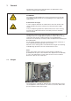

1.2 Description of the locking positions
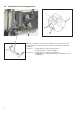
With the locking pin 1 and the arresting grooves 2 and 3 in the arm
shaft crank 4 the sewing machine can be arrested in two adjusting
positions.
Position I = Locking pin Ø 5 mm for large groove
= Looping stroke, needle bar height
Position II = Locking pin Ø 3 mm for small groove
= Needle bar at its upper dead center, graduation on the
handwheel
4
2
4
1
3