506-3 Instructions, complete Operating Instructions 1 Installation Instructions 2 Service Instructions 3 Postfach 17 03 51, D-33703 Bielefeld • Potsdamer Straße 190, D-33719 Bielefeld Telefon +49 (0) 521 / 9 25-00 • Telefax +49 (0) 521 / 9 25 24 35 • www.duerkopp-adler.com Ausgabe / Edition: 10/2008 Änderungsindex Rev. index: 01.0 Printed in Federal Republic of Germany Teile-Nr./Part.-No.
Instructions, complete 506-3 Overview Operating table Operating Instructions Installation Instructions Service Instructions Pneumatic circuit plan 9770 506002 Interconnection-diagram 9890 506003 B All rights reserved. Property of Dürkopp Adler AG and copyrighted. Reproduction or publication of the content in any manner, even in extracts, without prior written permission of Dürkopp Adler AG, is prohibited.
Foreword This instruction manual is intended to help the user to become familiar with the machine and take advantage of its application possibilities in accordance with the recommendations. The instruction manual contains important information on how to operate the machine securely, properly and economically. Observation of the instructions eliminates danger, reduces costs for repair and down-times, and increases the reliability and life of the machine.
General safety instructions The non-observance of the following safety instructions can cause bodily injuries or damages to the machine. 1. The machine must only be commissioned in full knowledge of the instruction book and operated by persons with appropriate training. 2. Before putting into service also read the safety rules and instructions of the motor supplier. 3. The machine must be used only for the purpose intended. Use of the machine without the safety devices is not permitted.
Contents Page: Preface and General Safety Information Part 1: Operating Instructions Cl. 506-3 (Edition 10/2008) 1. 1.1 1.2 1.3 Product Description Description of the Proper Use and Proper Application . . . . . . . . . . . . . . . . . . . . . . . . . Short Description . . . . . . . . . . . . . . . . . . . . . . . . . . . . . . . . . . . . . . . . . . . . . . . Technical Data . . . . . . . . . . . . . . . . . . . . . . . . . . . . . . . . . . . . . . . . . . . . . . . . 2. 2.1 2.2 2.3 2.4 2.
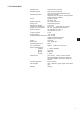
Noise level Lc Workstation related emission according to DIN 45635-48-B-1 -1 Number of stitches: 1.000 min Commanding cam: (Stitches) 116 Sewing cycles: 9,7 s on / 2,0 s off 2 Sewing material: 2x girdle tape 1,5 mm 1.
1. Product Description 1.1 Description of the Proper Use and Proper Application The 506-3 is a robust, heavy-duty, curve-guided single needle lockstitch short seam unit for seams of stitch type 301. This short seam unit is designed for use in sewing heavy-weight fabric, as well as thick and hard leather. Thick and hard leathers find use in the sewing on of trim pieces, in the sewing of buckle caps, tabs, suitcases, tarpaulins, knapsacks and backpacks.
1.2 Short Description Uniform Quality The unit always produces a uniform seam formation. The high thread tension necessary for the working of heavy materials is achieved through a hinged thread lever. Direct Power Transmission The power transmission from the motor to the arm shaft occurs via a special V-belt. This results in a particularly strong perforating power for the sewing of thick materials or multiple layers.
1.3 Technical Data Sewing area: Needle system: maximum 60 x 100 mm 428; 428 Serv Nm 250; 794 (for thick sewing material only) Needle thickness: Nm 120 - Nm 280 depending on the type of sewing thread and the sewing material. Yarns: Synthetic yarns Nm 30/3 - 8/3 Bobbin capacity: 23 m with 18/3 yarn Stitch type: Lockstitch type 301 Number of stitches: 1100 / min Number of stitches per 42, 58, 72 (without gear reducer) guide curve revolution: 84, 116, 144 (with gear reducer) Seam formation 72 stitches in 3.
Notes: 8
2. Operation 2.1 Automatic Sewing Sequence 2 1 3 1 5 4 ATTENTION ! The starting of a sewing sequence is only possible with the head cover 1 and cover 2 for the hook area closed. If the head cover or cover for the hook area is open all functions of the controls are blocked. Work procedure (in foot switch mode 1) – Turn the main switch 3 on. The clamps are in their upper position. – Select sewing program. – Align the sewing material under the clamps.
– – – – For a secure sewing-on pull the thread end hanging out of the needle to the side when starting the first sewing sequence and hold it tight. After the first stitches the thread can be released again. The automatic sewing sequence runs through according to the selected sewing program. For an exact description of the different sewing programs see “Quick User’s manual”. After the sewing sequence ends the clamps are raised automatically. Remove the sewing material.
2.2 Needles and Yarns Needle system: 428; 428 Serv Nm 250; 794 (depending on the type of sewing thread and sewing material used) Needle thickness: Nm 120 - Nm 280 (depending on the type of sewing thread and sewing material used) Yarns: Synthetic sewing yarns (30/3 to 8/3) Changing the needle: 2 1 1 A A A-A Caution Risk of Injury ! Turn the main switch off. Change the needle only with the unit turned off. – – – – – Open the head cover. Loosen screw 1. Remove the needle.
2.3 Threading the Needle Thread Caution Risk of Injury ! Turn the main switch off. Thread the needle thread only with the unit turned off. The threading of the needle thread 18 occurs as shown in the pictures alongside in increasing numerical order: – Place the yarn roll on the yarn stand. – Thread the thread through the holes 1 of the yarn stand. – Thread the thread through thread guide 2. – Lead the thread through between the tension disks of the first needle thread tension 3.
12 11 10 9 8 7 6 5 4 3 2 1 13 14 15 16 17 13
2.4 Changing the Bobbin 3 2 1 4 Remove the bobbin – Press button 2 on the sewing head or button “ ” on the control unit. – Hold on to cover 1 and push the locking lever 3 upwards to unbolt the cover. – Fold cover 1 forward and down. ATTENTION ! Cover 1 is monitored by a safety switch. With the cover open, all functions of the controls are blocked. Starting the sewing sequence after a change of bobbin is only possible with the cover closed.
10 6 9 8 7 1 Inserting a full bobbin – Place the full bobbin in the bobbin case 6. Here take care that when thread is being pulled off the bobbin must turn clockwise (see the arrow direction)! – Swing in the bobbin case 6. – Pull the thread through the slit 10 into the opening 9 on the spring 8. ATTENTION ! A thread sliding out of slit 10 can lead to missing stitches and needle breakage. Therefore pull the thread so far through slit 10 until it lies secure in the opening 9 on the spring 8.
2.5 Thread Tension Set the thread tensions appropriate to the yarn types and thicknesses used so that a clean seam formation results. Too high thread tensions cause a crimping of the sewing material. Too low a bobbin thread tension can lead to missing stitches. Setting the needle thread tension 1 2 – Set the upper needle thread tension by turning the knurled screw 1 and the lower needle thread tension by turning the knurled screw 2.
3. Bobbin winder 7 6 5 1 4 3 8 9 10 11 1 2 Reeling on the spool thread – Place yarn reel on reel stand. – Thread the thread through the holes 1 in the reel stand. – Pass the thread through the tension discs of tensioner 2. – Pass the thread through the tension discs of tensioner 3 of the reel. – Pass the thread through the slot in guide 4. – Pass the thread through the hole 7 in the empty reel. – Place the empty reel on the bobbin shaft 8.
4. Maintenance Caution Risk of Injury ! Turn the main switch off. Maintenance work on the unit may only be conducted with the machine turned off. 4.1 Cleaning A clean machine protects against malfunctions ! Daily cleaning: – Particularly the areas around the needle thread guides 1 and tensions, thread controller spring and hook 2 are to be cleaned of sewing dust and lint accumulations (e.g. with a compressed air gun). For cleaning the parts attached under the foundation plate tilt the machine head aside.
– Check the water level in the pressure regulator. The water level should not be allowed to rise to the filter insert 3. After screwing in the drain screw 5 blow the water out of the water separator 4 under pressure. Dirt and condensation water are eliminated through the filter insert 3. Wash out the dirty filter bowl and filter insert with naphtha after a certain period of operation and blow clean with compressed air. ATTENTION ! Do not use solvents for washing! They destroy the filter bowl.
4.2 Lubrication For lubrication of the machine use only DA-10 lubricating oil. DA-10 is available from DÜRKOPP ADLER AG retail outlets. Check the oil level in the oil reservoir of the oil mister The run of the barrel shuttle is lubricated and cooled by compressed air enhanced with oil from the oil mister. – The oil level in oil reservoir 5 must not fall below the suction tube 4. – If necessary, top up with oil to the upper edge of the embossed text 3. – For topping up screw out the oil filler screw 2.
Checking the oil level in the oil reservoir of the central lubrication unit The central recirculating-lubrication unit automatically supplies all the automatic sewing machine’s important lubrication points. – The oil level in oil reservoir 1 must not fall below the “min” mark. – If necessary, top up with oil to the “max” mark.
Notes: 22