
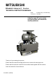
Instruction manual

- 4 -
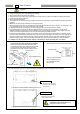
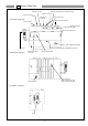
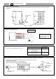
1. Front side of control box
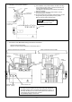
2. Back side of control box
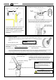
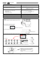
3. Left side of control box
4 Names of Each Part
Control switch panel
connector
Encoder connecto
r
Lever connector
Presser foot
connector
Sewing machine connector
Motor connector
White connector for 100V
Brown connector for 200V
Lever
Lever Unit
Power connector
Status indication LED
Connector indication
nameplate
High-voltage warning plate
XC-G10-S control switch panel installation screw hole
Front cover fixing screw
Detector connecto
r
Option A connecto
r
Option B connector
Protective cap (Remove the cap when using.)