
Instruction manual


- 33 -
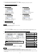
12. To check the error code history and input/output signal
(1) How to view the error code history ........... Function setting [1.E--], [2.E--], [3.E--], [4.E--]
(1)
Call out the program mode [E] function [1].
(This can be called with mode call or direct number call. Refer to
pages 14 to 16. (Direct call number = "0700"))
(2)
Call out function [1].
* The last error code is displayed.
(Ex. error code E1 is displayed.)
(3)
Call out function [2].
* The second to last error code is displayed.
(Ex. error code E3 is displayed.)
(4)
Call out function [3].
* The third to last error code is displayed.
(Ex. error code E8 is displayed.)
(5)
Call out function [4].
The fourth to last error code is displayed.
(Ex. error code E2 is displayed.)
(6)
Entering the normal mode
For mode call: [Ļ] + [Ĺ]
For direct number call: Press .
Description
A. 4 times errors from the last to the fourth error can be viewed.
B. Refer to page 44 for the error code.
(2) To check input signals
.......... Function setting [IA] - [IL], [I1] - [I5], [IP] - [IR], [ECA], [ECB], [UP], [DN], [DR], [VC], [V2]
(1)
Call out the input signal in program mode [E] to be checked. (In this example, call out [IA].)
(This can be called with mode call or direct number call. Refer to pages 14 to 16. (Direct call number = "0706"))
(2)
* Turn the input for the input terminal to be viewed ON and OFF, and confirm
that the LED C.D changes between [ON] and [OF].
* If the input to be viewed is UP or DN, turn the sewing machine shaft. If ECA
or ECB, turn the motor shaft.
To turn the signals related to the sewing machine
operation ON and OFF when the signal is turned ON
and OFF, normal operation will take place.
(3)
Entering the normal mode
For mode call: [Ļ] + [Ĺ]
For direct number call: Set with and then press .
Input signal
(Factory setting)
Display
Variable speed run signal (S1)
IG
Thread trimming (S2)
IH
Presser foot lifter (S3)
II
Presser foot lifter signal (F)
IF
Thread trimmer cancel signal (TL)
ID
Backstiting signal (S7)
IE
Needle UP position priority stop signal
(PSU)
IA
Needle DOWN position priority stop
signal (PSD)
IB
Low speed run signal (S0) IC
Input signal (IO1) I1
Needle lift signal (U) I2
No setting (NO) I4
No setting (NO) I5
Encoder signal display (A phase)
ECA
Encoder signal display (B phase)
ECB
Detector signal display (UP signal) UP
Detector signal display (DOWN signal) DN
Display the angle from down position
DR
Display the voltage of VC
VC
Display the voltage of VC2
V2
Description
A. It is possible to check whether or not input signal is wired right.
When the display is not turned [ON][OF] even if the signal is turned ON/OFF, check wiring to a control box from the signal.
Note that the sewing machine will run when checking the input of signal terminals related to operation.
B. Refer to the "Connector layout" on page 42 for the input terminals, and the technical information manual for details on the input
function names.
Caution