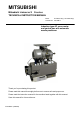
MITSUBISHI Mitsubishi Limiservo X G series TECHNICAL INSTRUCTION MANUAL Motor XL-G554-10(Y), XL-G554-20(Y) Control box XC-GMFY Induction type AC servo motor and control box with automatic needle positioner Thank you for purchasing this product. Please read this manual thoroughly before use to ensure safe and proper use. Please read the instruction manual for the machine head together with this manual. Save this manual for future reference.
1 1 2 3 4 5 Contents Contents ······························································································································································· 1 Safety Instructions················································································································································ 2 Points of Caution ······································································································································
2 Safety Instructions 1. To ensure safe use *Always observe the following items to ensure safe use of the industrial sewing machine drive unit (motor and control box). 1.1 Before starting Read all instruction manuals thoroughly before starting use of this drive unit, and follow the technical manuals. Also read the instruction manuals for the installed sewing machine. 1.2 Application and purpose This drive unit is designed to drive a sewing machine and must not be used for other applications or purposes.
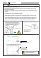
3 Points of Caution Caution 1. Please remove your foot from the pedal when turning the power ON. 2. Always turn the power OFF when leaving the machine. 3. Do not inspect the control circuit with a tester. 4. Always turn the power switch OFF before tilting the sewing machine, replace the needle or threading the needle. 5. Always ground the grounding wire. 6. Do not use branched wiring. 7.
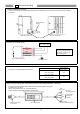
4 Names of Each Part Detector connector Encoder connector Protective cap (Remove the cap when using.) Option A connector Presser foot connector Option B connector 1. Front side of control box Sewing machine connector Lever connector Connector indication nameplate Front cover fixing screw High-voltage warning plate XC-G10-S control switch panel installation screw hole Lever Unit 2.
5 Installation 1. Installation of the motor 2. Installation of the control box Table (1) Tighten the control box onto the motor. The direction of the plate 3-9 holes 159 57 Encoder cord 66 Belt hole Bobbin winder (2) Insert the power cord from the motor into the connector on the back of the control box. Insert the encoder cord from the motor into the encoder connector on the front of the control box.
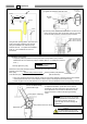
5. Installation of the protective cover (with belt slip off prevention part) The protective cover is enclosed with the motor as an accessory. 1. Install the protective cover A onto the motor. 2. Install the pulley and attach the belt. (Refer to "3. Installing the pulley" and "4. Mounting of the belt".) Nut Belt Protective cover A Pulley Tightening bolt 3. Install the "belt slip off prevention part mounting plate" onto protective cover B with the following procedures.
6. Installation of the position detector Position detector Stopper Grounding wire (green/yellow) (1) The installation of the position detector will differ according to the sewing machine model, so please consult with your sewing machine dealer for details. The diagram on the left shows an example of the position detector installation. (2) Insert the connector from the position detector into the control box position connector.
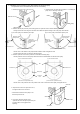
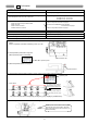
6 Wire and Grounding 1. Insertion of the power connector Confirm the connector form and insertion direction when inserting the power connector into the control box and insert completely. Power connector (6-Pole) Right side of control box Back side of control box Power connector 3-phase power 2. Connection of 3-phase power RSTphase phase phase Red Ground the green (green/yellow) wire to the grounding terminal. Consult with an electrician for the grounding wires.
7 Confirmation 1. Before turning switches on.......... Places to confirm Reference (1) Is the power and capacity suitable ? Current capacity on page 8. (2) Is the power voltage the same as the factory preset voltage of the rated nameplate on the side of the control box? Voltage value given on rated nameplate on side of control box. XC-GMFY-20-05 : 200 to 240V XC-GMFY-10-05 : 100 to 120V (3) Are the connectors inserted correctly? Insertion of the power connector on page 8.
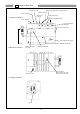
8 Adjustments 1. Adjustment of stopping position Sewing machine pulley Adjust this position with the detector installed onto the sewing machine and while stopping at the UP and DOWN positions. For safety, disconnect the connector for the sewing machine. (1) Adjustment of UP position -Loosen the two set screws on the detector joint, and set the stop position by rotating by hand.
3. Adjustment of operation speed Adjustment of each speed L - 4000 250 T - 200 H N V S Page25 “To change the maximum speed” 1700 1700 250 Adjust between the low speed [L] and high speed [H] using the [C] and [D] keys on the operation panel. - It is possible to adjust between 0 and 99.
9 Changing the solenoid voltage and output voltage 1. To change solenoid voltage DC24V/DC30V Control box side To change solenoid voltage from 24V to 30V (1) Remove the front cover from the control box. (2) Reconnect the connector inserted in JP1 on the PCB to the 30V side. (3) Set the cover to the original position after change. To change solenoid voltage from 30V to 24V (1) Remove the front cover from the control box. (2) Reconnect the connector inserted in JP1 on the PCB to the 24V side.
10 Operation of the Control Switch Panel Keys(When using XC-G10 type operation 1. Displays during normal mode and functions of each key When the power supply switch is turned ON, the rotation direction will display on the LED.M shown below. When the rotation direction is not displayed on LED.M, press the [↓] key any time. This state is called the normal mode, and the following keys can be operated. LED.M The rotation direction of the sewing machine is displayed.
(2) Selection of each program mode from the normal mode. Mode name Key operation Return to the normal mode Digital display Tacking type setting mode Press the [↑] key one time from the normal mode. No. of tacking stitch setting mode Press the [↑] key two times from the normal mode. *The tacking setting mode will be entered. *The tacking stitches setting mode will be entered. Press the [↓] key one time. Press the [↓] key two times. Note) Skipping about this menu at the time of pattern No.=4.
(3) Direct number call function (Directly selecting program mode function item from normal mode) The number of each function listed in section "13 List of functions" can be directly designated to call the function item. [Basic procedures] (1) (1000th) (100th) (10th) (2) (1st place) 、 、 、and Press the display the target function item number.
Status transition diagram (Direct number call operation) Normal mode Parameter Setup Parameter Setup Number call mode Number selection mode + Press simultaneously : Cancels changed value Select in all mode ranges Change number with "+" and "-" keys Select in [P] mode range Each function item Change number with "+" and "-" keys Select in [A] mode range :Sets changed value Change number with "+" and "-" keys Parameter Setup :Cancels changed value ・ ・ ・ Possible to select A to S mode Select in
4. Changing to the tacking, preset, pattern NO. selection mode Tacking mode [↑]key ON Normal mode [↓]key ON Tacking setting mode * Setting of the start tacking validity and type * Setting of the end tacking validity and type [↑]key [↑]key ON ON No. of tacking stitch setting mode [↓]key ON [↓]key ON Preset stitching setting mode * Setting of the preset stitching validity and No. of stitches [↑]key ON Pattern No. selection [↓]key ON Note) At the time of pattern No.
(3) Preset stitching setting mode The preset stitching setting mode is entered when the [↑] key is turned ON again. The validity of preset stitching and the number of stitches N can be set. (1) When the pattern is the time except pattern No.4 Start tacking S Factory setting Start tacking that is in the tacking mode N stitches will start at the S position. End tacking that is in the tacking mode Setting of preset stitching E Setting of No.
5. Using the program mode [1] simple setting To set the settings to a specific machine in simple setting. (For example, to set to "LU2-4410-B1T" ... Function setting [410B]) (1) (2) *Enter the program mode [1]. ([↓] + [A] + [B] keys) *The mode will change to the program mode [1]. (3) (4) *Press the [↓] key or [↑] key to change the function to [410B]. *When the [D] key is held down, [410B] will flicker, and the changes to the setting will be set.
Simple setting table for Mitsubishi thread trimming sewing machine and motor pulley outside diameter.
6. Using the program mode [2] simple setting (for chain stitch trimming machine) To set the function for chain stitch sewing machine in simple setting. (Ex. To set for the VC2800, VC3800 class, "YAMATO") .......... Function setting [YU4] (1) (2) *Enter the program mode [2]. ([↓] + [C] + [D] keys) *The mode will change to the program mode [2]. (3) (4) *Press the [↓] key or [↑] key to change the function to [YU4].
Simple setting table for chain stitch sewing machine Function name *1 Digital display Sewing machine maker Model name of sewing machine and device High speed (H) Thread Start con- End conLow speed trimming densed densed speed speed speed (L) (N) (V) (T) YU2 YAMATO VC2600, VC2700 class Solenoid-operated under thread trimmer 2 6000 200 200 1400 1400 YU3 YAMATO VC2600, VC2700 class Air-operated under thread trimmer with air wiper 2 6000 200 200 1400 1400 YU4 YAMATO VC3845P,2845P,2840P
7. Using the program mode [3] simple setting (for lock stitch trimming machine except Mitsubishi sewing machine) To set the function for DÜ RKOPP ADLER thread trimming sewing machine in simple setting (For example, to set for the 271 class, "DÜ RKOPP ADLER") .......... Function setting [D271] (1) (2) *Enter the program mode [3]. ([↓] + [A] + [D] keys) *The mode will change to the program mode [3]. (3) (4) *Press the [↓] key or [↑] key to change the function to [D271].
Simple setting table for thread trimming sewing machine Function name *1 Thread Start End Low tacking tacking speed trimming speed speed speed (L) (T) (N) (V) Needle position High speed (H) 697-15000 class 2 1500 250 150 700 700 271-14000,272-14000 class 2 3000 170 250 1500 1500 Sewing machine maker Model name of sewing machine and device 273-14000,274-14000 class 2 3000 170 250 1500 1500 B715 DÜRKOPP ADLER DÜRKOPP ADLER DÜRKOPP ADLER BROTHER DB2-B705,DB2-B707,DB2-B715 class 2
11 Example of setting the program mode 1. To change the maximum speed (Ex. to change to 3500 rotations) ............ Function setting [H.3500] (1) Call out the program mode [P] function [H]. (This can be called with mode call or direct number call. Refer to pages 14 to 16. (Direct call number = "0000") ) (2) Press the [+] and [-] keys ([A], [B], [C], [D]), and set to "3500". (3) Entering the normal mode For mode call: [Ļ] + [Ĺ] For direct number call: Set with and then press . Description A.
3. To operate Half-stitch operation with a backstitching switch .......... (1) Function setting [IE.UDS] Call out the program mode [C] function [IE]. (This can be called with mode call or direct number call. Refer to pages 14 to 16. (Direct call number = "0312")) (2) *Press the [D] key and set to "UDS" for the setting value. (3) Entering the normal mode For mode call: [Ļ] + [Ĺ] For direct number call: Set with and then press . Description sewing machine connector A.
5. Setting the number of stitches to the UP position stop after fabric end is detected with optical sensor, etc. ........ Function setting C mode [IA. PSU] and P mode [PSU.10] (Example: Setting to 10 stitches) (1) (2) Call out the program mode [C] function [IA]. (This can be called with mode call or direct number call. Refer to pages 14 to 16. (Direct call number = "0300")) * Press the [D] key and set the value to "PSU". (3) Set the function [IA] settings.
6. To continue presser foot lifting after the thread trimming, and to bring down the presser foot after the time set on the timer has passed .......... Function setting [FUM.ON]+ [FU.C] (1) Call out the program mode [P] function [FUM]. (This can be called with mode call or direct number call. Refer to pages 14 to 16. (Direct call number = "0021")) (2) *Press the [D] key and set to "ON" for the setting value. (3) Call out the program mode [P] function [FU].
8. To display the rotation speed on the control switch panel ........... Function setting [S.****] (1) Call out the program mode [B] function [S]. (This can be called with mode call or direct number call. Refer to pages 14 to 16. (Direct call number = "0200")) (2) * The rotation speed is indicated as "0" when the sewing machine stops. (3) * For example, if the maximum speed setting is 4000 rotations, the displayed speed will be [S.4000] when the pedal is fully toed down as shown above.
9. To adjust the tacking accurately (1) To adjust tacking surely .......... Function setting [D1. CST] + [CT. 10] (To set the stop time at each tacking corner to 100 msec.) (1) (2) Call out the program mode [D] function [D1]. (This can be called with mode call or direct number call. Refer to pages 14 to 16. (Direct call number = "0600")) *Press the [D] key and set to "CST" for the setting value.
10. Setting the tacking stitch correction To correct when the set number of tacking stitches does not match the number of actual stitches .........Function setting [BT1.4] + [BT2.4] + [BT3.8] (To stitch three start and end tacking stitches (Fig. 1), but actual stitches as shown in (Fig. 2).) Fig. 2 Fig. 1 (1) Call out the program mode [D] functions [BT1] to [BT3]. 4 (This can be called with mode call or direct number call. Refer to pages 14 to 16.
11. Example of setting counter function (Refer to the Technical Documents for details on setting the up counter.) * When using down counter as a bobbin thread level counter (Ending count after 10,000 stitches) (1) The current down counter value [D] is decremented by one each time ten stitches are stitched. (2) When the remaining down counter [D] reaches 0, stitching is prohibited after trimming (Stitching is possible until the thread is trimmed.
12. To check the error code history and input/output signal (1) How to view the error code history ........... Function setting [1.E--], [2.E--], [3.E--], [4.E--] (1) Call out the program mode [E] function [1]. (This can be called with mode call or direct number call. Refer to pages 14 to 16. (Direct call number = "0700")) (2) (3) Call out function [1]. Call out function [2]. * The last error code is displayed. (Ex. error code E1 is displayed.) (4) * The second to last error code is displayed. (Ex.
(3) To check output signal (check in operation) .......... Function setting [OAD] - [ODD], [OFD], [OPD] - [ORD], [O1D] - [O7D] (1) (2) Call out the output signal in program mode [E] to be checked. (In this example, call out [OAD].) (This can be called with mode call or direct number call. Refer to pages 14 to 16.
13. To return all settings to the factory settings .......... Function setting [RESET] (1) (2) * Enter program mode [R] ([Ļ] + [B] + [C] keys) * Program mode [R] will be entered. (3) (4) * [RESET] will flicker when the [D] key is held down, and the reset process will be executed. * The data will be set to the factory setting when the [D] key is pressed over 2 seconds or more, and then the normal mode will be returned to. (Process is completed) Description A.
14. To adjust the position data for the lever unit ... Function setting [VCSET] (When error "MA" is displayed) (1) Set the pedal (lever unit) to the neutral position. (2) Call out the program mode [Q] function [VCSET]. (This can be called with mode call or direct number call. Refer to pages 14 to 16. (Direct call number = "1427")) * Enter program mode [Q] ([Ļ] + [A] + [C] keys) (3) (4) [VCSET] will flicker when the [D] key is held down. (5) Fully toe down the pedal (lever unit).
12 To save the setting data 1. How to use the program mode [I] To save the setting data ........... Function setting [SAVE*] (Two types of data, [SAVE1] and [SAVE2] can be saved. The [SAVE1] data can be read out with [LOAD1], and the [SAVE2] data with [LOAD2].) (1) (2) * Enter program mode [I] ([↓] + [↑] + [B] + [C] key) * Program mode [I] will be entered. (3) (4) * When the [D] key is held down, [SAVE1.] will flicker, and the save process will be executed.
13 Function List FD. FO. S3D. FUD. PFU. FL. S3L. S2L. S6L. AT. TL. TLS. RU. R8. TB. TBJ. S2R. IL. TR. POS. P1P. P2P. C8. K8. E8. S8. SNM. KD. KDU. PSJ. D8. U8. Function Maximum speed Low speed Thread trimming speed Start tacking speed End tacking speed Medium speed Slow start speed No. of slow start stitches Slow start operation mode Slow start when power is turned ON One shot One shot operation mode No. of stitches after PSU input No.
Function IA input function selection IA input logic changeover IA input alternating operation IB input function selection IB input logic changeover IB input alternating operation IC input function selection IC input logic changeover IC input alternating operation ID input function selection ID input logic changeover ID input alternating operation IE input function selection IE input logic changeover IE input alternating operation IF input function selection IF input logic changeover Setting the function for
C mode (For setting input/output signal to function): [↓]+[C] key OTT. FCT. A1. A1L. A1A. N1. N1L. N2. N2L. A2. A2L. A2A. N3. N3L. N4. N4L. A3. A3L. A3A. N5. N5L. N6. N6L. OR. ORL. ORA. R1. R1L. R2. R2L. CSP. CSG. LB. T1C. T1T. T2C. T2T. T3C. T3T. D11. D12. D21. D22. D31. No. 0456 0457 0458 0459 0460 0461 0462 0463 0464 0465 0466 0467 0468 0469 0470 0471 0472 0473 0474 name D32.
E mode (For H/W checking mode): [↓]+[↑]+[A] key name 1. 2. 3. 4. P. M. IA. IB. IC. ID. IE. IF. IG. IH. II. IJ. IK. IL. IP. IQ. IR. I1. I2. I4. I5. ECA. ECB. UP. DN. DR. VC. V2. OAD. OBD. OCD. ODD. OFD. O1D. O2D. O3D. O4D. O5D. O6D. O7D. OPD. OQD. ORD. OAO. OBO. OCO. ODO. OFO. O1O. O2O. O3O. O4O. O5O. O6O. O7O. OPO. OQO. ORO. WT. VL. TP. DV. RV. T.
14 How to Use the Option Connector Variable operations are possible by adding external signals to the option connector. A current of approximately 1.5 mA flows through the switches used for the input signal, so please use switch for minute current. 1.
2. To use as a standing work type sewing machine. (Turn the program mode [C] function [PDS] ON.) The sewing machine can be used as a standing work type sewing machine with the three connections below using the lever connector. However, take special care to the intrusion of noise, and use the shortest wiring possible. 【Note: Procedure for changing the lever connector】 ■ Be sure to turn OFF the power switch when connecting or disconnecting the lever connector.
15 Error Display When the control box detects an error, the error code is flickered on the control switch panel display. Confirm the error code, and investigate with the following table. Probable cause Error code /POWER.OF / E1 / E2 / E3 Check the power voltage. Is the power supply capacity too small? Check the power supply capacity. Note: It does this display when power supply is turned OFF, but this is not an error. Is the wire to the motor short-circuited? Check the motor wiring.
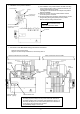
16 Specifications Voltage and Frequency Specifications Motor Control box 110V single phase 50/60 Hz 230V single phase, 3-phase 50/60 Hz XL-G554-10 (Y) XL-G554-20 (Y) Model name Voltage Rated output Rated torque Rated speed Weight General purpose Model automatic thread name trimmer Voltage Sewing Speed control machine range shaft Motor shaft Solenoid voltage Range of rating Voltage Ambient temperature Ambient humidity Storage temperature Altitude Weight Position detector 100 to 120 V 200 to 240 V
Dimensions *MOTOR and CONTROL BOX 187 121 33 33 screw 36 Taper shaft 13 66 159 57 28.5 278.5 221 85.5 74 120 12 251 Φ104 181 102 14.
MITSUBISHI ELECTRIC CORPORATION FACTORY AUTOMATION SYSTEM TOKYO BLDG.