
User Manual
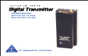
DTC COMMUNICATIONS, INC.
9
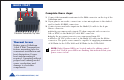
COMPONENTS
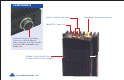
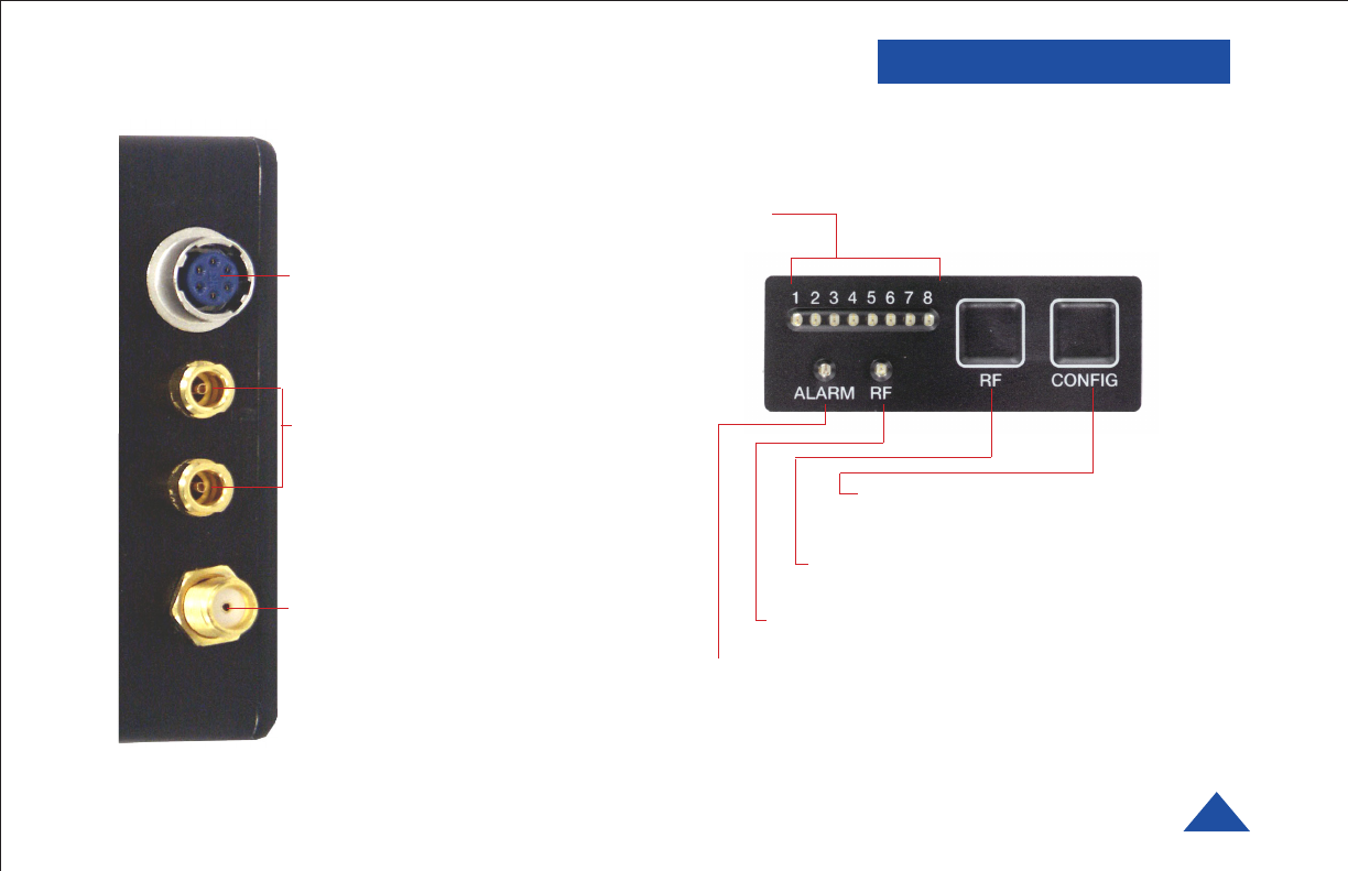
Audio 1 and 2 Connectors (LEMO)
These connectors provide the
microphone connections to the
transmitter. Either one or two
microphones can be used with the
Palladium Transmitter.
Transmitter Antenna Connector
(SMA) This connector attaches to
the transmitter antenna and carries
the RF output signal. Always ensure
the transmitter antenna is attached
before operating the Palladium
Transmitter.
Muiti I/O Connector (6-pin Hirose)
This connector provides
connections for the DC power input,
programming, and 75 Ohm
composite video signal.
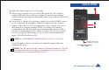
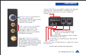
ALARM LED This red LED indicates a valid video signal
is not present.
RF Button This membrane switch toggles
ON/OFF the RF output.
Channel LEDs These green LEDs, numbered 1 through
8, indicate the channel number currently selected.
Each channel represents a set of preconfigured
settings.
CONFIG Button This membrane
switch cycles through the eight
channels.
RF LED This green LED indicates that the RF
output is ON.
Control Panel (located under sliding door)