
Specifications


DSX Access Systems, Inc. 10731 Rockwall Road Dallas, Texas 75238 / 888-419-8353 / 214-553-6140 / www.dsxinc.com
11/2012
The DSX-1040PDP houses the controller and lock power
supplies, backup batteries, and fused power distribution
module. The DSX-1040PDP is comprised of a DSX-1040PE
Enclosure, an SWS-150 15V power supply for the controllers,
an SWS-150-[15] or [27] for either 12Vor 24V locks, and a
DSX-1040PDM Power Distribution Module. The DSX-
1040PDM performs several critical functions. First, it takes the
15V power from the SWS-150 and provides two 3A Class II,
Power Limited, fused outputs to power the DSX-1040CDM
which distributes the power to the DSX-1042 Controllers in
the DSX-1048PKG. It provides a 12VBattery Charging Circuit
to charge backup batteries for the controllers. It also provides a
charging circuit for the optional batteries used to backup the
12 or 24 volt lock power from the SWS-150 lock power
supply. The Power Distribution Module has 3 N.C. Relay
Outputs, two to signal Loss of AC (one for lock power and one
for controller power) and one to signal Low Battery. These
Outputs can be connected to spare Inputs in the DSX-
1048PKG. The module also has a Battery Test Input. This
Input when activated shuts off the charging circuit and load
tests the battery for 1 minute. This Input can be connected to a
spare Output in the DSX-1048PKG and programmed by time
zone to occur when desired. The DSX-1040PDM routes Lock
Power through individual fuses for each of the 8 Class II,
Power Limited, outputs. The module also has an input for a
Fire Override relay contact to break Lock Power and has a Fire
Override Output to connect to the next 1040PDM. All Outputs
are Class II, Power Limited.
Reader Technologies
The DSX-1048 is compatible with Wiegand, Barium Ferrite,
Proximity, Bar Code, Magnetic Stripe, Biometric, and Smart
Card readers. Any combination of reader technologies may be
used in the same system. A keypad may be added to most
readers to create a card and/or PIN controlled entry point. The
DSX-1048 is compatible with over 240 different card readers /
keypads and card formats which make it the perfect panel for
retrofits. Conversion modules exist for some types of other
manufacturers proprietary card readers. The panel is
compatible with two wire wiegand and clock and data outputs
without the use of any modules. Each reader port has 3 LED
open collector outputs for Door Secure, Door Open, and
Access Denied/Keypad PIN Entry. This will accommodate
almost any reader and LED configuration. It is possible to
connect the sounder control line of most card readers directly
to the Pre-Warn output for door held open annunciation.
Memory
Each Controller has a standard configuration of 512K of Flash
ROM and 512K of RAM. The RAM memory allocation is
dynamic between database and event storage and set for
optimum use by the Host PC according to data entered for that
location. Flash ROM allows for the Controllers’ operating
system to be upgraded without the changing of chips
(EPROMS). Having 512K of RAM eliminates the necessity of
increasing the memory in controllers as the system grows.
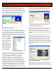
When the Controller is in service the amount of RAM and the
version of ROM can be viewed from the DSX
communications software.
Inputs
The DSX-1048PKG has 32 EOL supervised Inputs capable of
two, three, and four state point monitoring with trouble
reports. The armed status of each Input can be controlled by up
to 4 Time Zones, I/O & Card Linking, and Manually from the
PC. Eight Inputs are designated as Door Position and eight
Inputs are designated as Exit Request Inputs for the reader
controlled doors. The remaining sixteen Inputs are then left for
additional monitoring points.
Outputs
The DSX-1048PKG has 16 Programmable Outputs. Eight
Outputs are Form-C, 5 Amp rated relays used to control the
locks for the reader controlled doors. Eight Outputs are the
open collector type, both have an LED for status and are fully
programmable. In addition to the 16 programmable Outputs
there are 8 Pre-Warn Outputs, (1 for each door) and are used to
indicate the reader controlled doors are being held open and
are about to go into alarm. Once the door is opened the Output
begins pulsing low starting at 1/3 of the door open too long
time and changes to a steady low anytime the door is in alarm.
These open collector (switched negative) outputs reset
automatically when the door is closed.
Communications
The DSX-1048PKG Intelligent Controller can communicate
with the WinDSX Communications Server via TCP/IP LAN
communications, Direct Serial Port connection, and Dial-Up
Phone Modem. TCP/IP LAN Communications can be
performed from the WinDSX Comm Server PC to a Master
Controller. The WinDSX Software without the use of any
additional Hardware or Software will redirect what would
typically be serial port communications to a TCP/IP address. A
DSX-LAN(M) serial device at the Master Controller receives
the communications over the LAN from the WinDSX PC and
converts it to RS-232/RS-485 for the Master Controller. The
end result is real time communications similar to that of a
direct serial port connection.
Direct Connect Communications from the PC to the Master
Controller is performed with a connection from the Host Port
of the Master to a USB port of the PC. RS-232 is used for
short distance connections. RS-485 communications is used
when the direct serial port connection is from 50 to 4000 feet
from Controller to PC. In order to communicate with the
Master Controller with RS-485 communications requires
two MCI modules. One DSX-USB module is placed at the PC
to convert the USB to RS-485 and a DSX-MCI (second
module) is placed at the Master Controller to convert the RS-
485 back to RS-232. The Controller communicates with the
PC at a default baud rate of 9600.