
Operating Instructions and Installation Instructions


Installation & Programming Manual
54
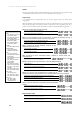
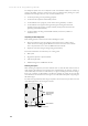
Extension 14 is suitable for external wiring and is fitted with the required protection circuitry.
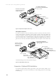
Figure 4-3 below, shows the terminal layout.
Figure 4-3 MDF connections
Extension wiring
To eliminate cross-talk, it is a requirement that twisted pair cable must be used to support
all extensions and system integral devices with only one extension per cable. Four-wire
cable must be used.
If an ordinary telephone is connected to an extension which previously had a Terminal connected,
the system needs to be told that the Terminal is no longer connected. Ringing will not be heard at the
extension until this has been done, though dialling will still be possible. After plugging in the SLT, go
off-hook and enter the code *750 ext #.
Important!
Important!
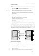
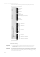
Powerfail connections
(
PSTN onl
y)
Paging port
Door 2 latch relay
Door phone 2 (option)
Not used
2
1
Door phone 1
Door 1 latch relay
24
23
22
21
18
17
16
15
14
13
12
11
1
2
3
4
5
6
Terminal Signalling (4 pairs in parallel)
DrRly_Dr1v
CO4__CO3
-Tx+ -Rx+
CO2__CO1
Pfail Pfail
Ext11_Ext12
Ext13_Ext14
Ext15_Ext16
Ext17_Ext18
Pfail
Ext21_Ext22
Pfail
Ext23_Ext24
CO6__CO5
-Tx+ -Rx+
TerSig1_Sig2 AuxSig1_Sig2 Dr2v_Page Alm1_Alm2 Alm3_Alm4
AlmRly
C NC C NO
Extensions Miscellaneous Exchange Lines Alarms
Alarm Loops
Expansion slot 1
Expansion slot 2
Basic system
Expansion slot 2 ISDN or PSTN
Expansion slot 1 ISDN or PSTN
Basic system