DSS NETWORKS GigMAC PMC/PCI Controllers Board and Driver Users Manual (Includes models 5161, 5162, 5164, 5261, 5262, 6161, 6167, 6162 and 7160) Document Version 2.
GigMAC PMC and PCI Board and Driver Users Manual 1. INTRODUCTION..................................................................................................................... 3 1.1 SEE ALSO............................................................................................................................. 3 1.2 COMPATIBILITY ................................................................................................................... 4 2. MODEL NUMBERS..................................
GigMAC PMC and PCI Board and Driver Users Manual 1. INTRODUCTION The GigMAC family of network controllers are a high-performance, cost-effective solution for adding Gigabit Ethernet connectivity to any embedded or real-time Network Appliance, Switch, Router, Server or other access device equipped with a PCI or PMC Mezzanine slot and is ideal for PCI, CompactPCI, PMC Mezzanine and other embedded systems.
GigMAC PMC and PCI Board and Driver Users Manual 1.2 COMPATIBILITY The GigMac family is fully compliant with the following standards: IEEE 802.3 (all sections applicable to 1000 Base T, 1000 Base SX, 1000 Base LX) IEEE 802.1D and IEEE 802.1Q as applicable for VLAN and priority queuing support PCI 2.2 bus compliant PCI low-profile specification (as applicable for model) IEEE 1386.1 Draft 2.2 Linux driver compatibility: Standard Linux 2.2 or 2.
GigMAC PMC and PCI Board and Driver Users Manual 3. FEATURES The GigMac adapter offers the following key features: • • • • • • • • • • • • • • • • • Sustained throughput of 245 Mbytes/sec (1.96 Gb) over PCI bus using 64bit, 66 MHZ PCI Sustained throughput of 118 Mbytes/sec (944 Gb) over PCI bus using 32bit, 33 MHZ PCI Frame processing rate of up to 1,000,000 frames per second (as measured on 2 GHZ P4/Zeon running Linux 2.
GigMAC PMC and PCI Board and Driver Users Manual TCP/UDP/IP performance test programs (vxWorks, Linux, Windows versions included) TCP, UDP and raw driver performance tests Driver Utilities (Linux) High-performance frame generator (wire and bus-speed capable) Transmit and receive callbacks (hooks) for driver-level application code Internal and external loopback capabilities Built-in performance instrumentation statistics Gigabit Ethernet FAQ sheet NetPerformance.
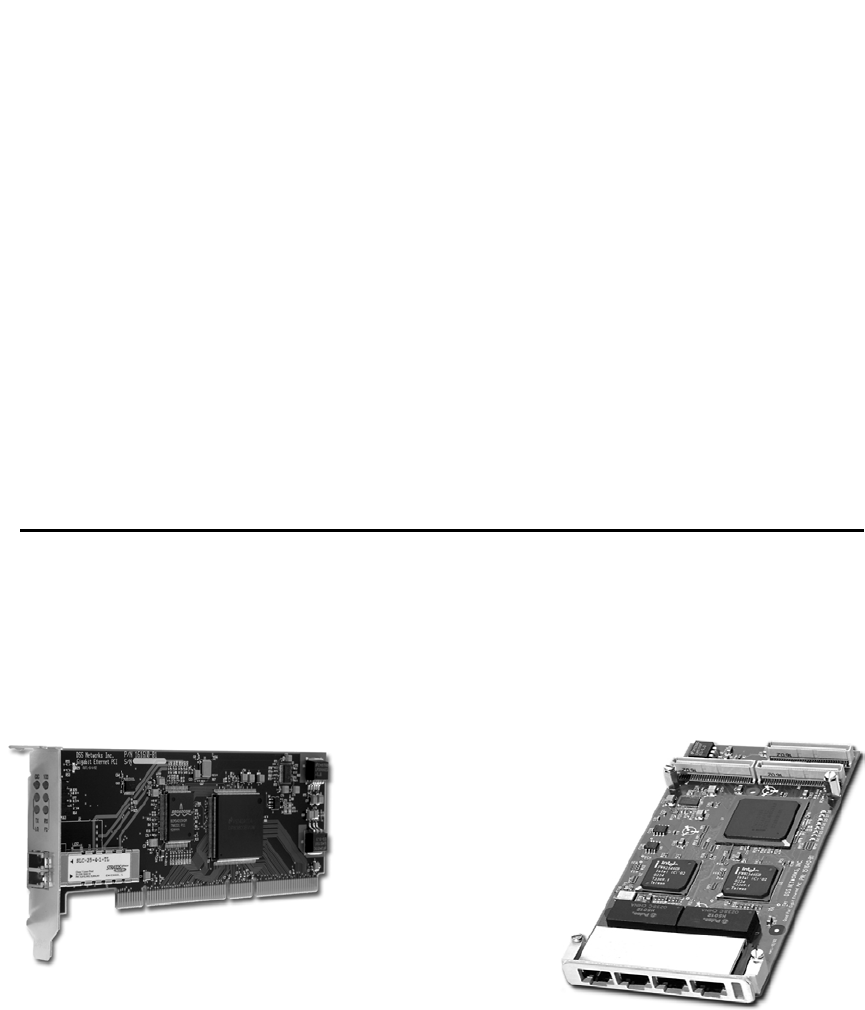
GigMAC PMC and PCI Board and Driver Users Manual 6. BOARD AND CONNECTOR INFORMATION 6.1 BOARD PHOTOS Model 5162 - 2-port PMC Model 5161 PMC Model 5164 - 4-port PMC Model 7160 Fiber PMC Model 6162 PCI-X - 2-port Model 6167 Fiber PCI DSS NETWORKS, INC. Model 6161 PCI Version: 2.
GigMAC PMC and PCI Board and Driver Users Manual 6.
GigMAC PMC and PCI Board and Driver Users Manual Full-Duplex LED illuminates solid yellow to indicate full duplex status Transmit and Receive Activity Indicators Transmit and Receive LEDs are on solid or blinking green to indicate activity on the link (solid shows constant activity, blinking shows intermittent activity) Model 7160 with SC or LC connector The front panel has onboard fiber optic connectors that supports the connection of fiber optic cabling using 50 or 62.
GigMAC PMC and PCI LED_ACT LED_LINK LED_1000 LED_100 Board and Driver Users Manual (activity) (link) (1000 Mb mode) (100 Mb mode) Model 5162 dual-port PMC with RJ-45 connector(s) The front panel has two onboard RJ-45 connectors that supports the connection of Category 5 cabling with 4 LED indicators per port that provide the following as marked with silkscreen nomenclature on front panels: LED_1000 LED_FD LED_TX LED_RX (1000 Mb mod) (full-duplex mode) (transmit activity) (receive activity) Model 5262
GigMAC PMC and PCI Board and Driver Users Manual 6.3 PMC CONNECTOR PIN/SIGNAL DEFINITIONS PMC Connectors Pin Assignments Pn1/Jn1 32 Bit PCI 1 TCK 3 GND 5 INTB# 7 BUSMODE1# 9 NC INTD# 11 GND 13 CLK 15 GND 17 REQ# 19 VIO 21 AD[28] 23 AD[25] 25 GND 27 AD[22] 29 AD[19] 31 NC VIO 33 FRAME# 35 GND 37 DEVSEL# 39 GND 41 NC SDONE# 43 PAR 45 NC VIO 47 AD[12] 49 AD[09] 51 GND 53 AD[06] 55 AD[04] 57 NC VIO 59 AD[02] 61 AD[00] 63 GND DSS NETWORKS, INC.
GigMAC PMC and PCI Pn2/Jn2 32 Bit PCI 1 NC +12V 3 TMS 5 TDI 7 GND 9 NC PCI-RSVD 11 NC BUSMODE2# 13 RST# 15 3.3V 17 NC PCI-RSVD 19 AD[30] 21 GND 23 AD[24] 25 IDSEL 27 +3.3V 29 AD[18] 31 AD[16] 33 GND 35 TRDY# 37 GND 39 PERR# 41 +3.3V 43 C/BE[1]# 45 AD[14] 47 M66EN 49 AD[08] 51 AD[07] 53 +3.3V 55 NC PMC-RSVD 57 NC PMC-RSVD 59 GND 61 ACK64# 63 GND DSS NETWORKS, INC. Board and Driver Users Manual TRST# TDO GND PCI-RSVD PCI-RSVD +3.3V BUSMODE3# BUSMODE4# GND AD[29] AD[26] 3.
GigMAC PMC and PCI Pn3/Jn3 32 Bit PCI 1 NC PCI-RSVD 3 GND 5 C/BE[6]# 7 C/BE[4]# 9 NC VIO 11 AD[63] 13 AD[61] 15 GND 17 AD[59] 19 AD[57] 21 NC VIO 23 AD[55] 25 AD[53] 27 GND 29 AD[51] 31 AD[49] 33 GND 35 AD[47] 37 AD[45] 39 NC VIO 41 AD[43] 43 AD[41] 45 GND 47 AD[39] 49 AD[37] 51 GND 53 AD[35] 55 AD[33] 57 NC VIO 59 NC PCI-RSVD 61 NC PCI-RSVD 63 GND DSS NETWORKS, INC.
GigMAC PMC and PCI Board and Driver Users Manual 7. POWER CONSUMPTION SPECS PCI / PMC Boards Power Consumption Table Gigabit NIC Model PCI 6161 PCI 6167 PCI-X 6162 PMC 5160 PMC 5161 PMC 7160 PMC 5162 PMC 5164 3.3V Source Current I (mA, A) 5V Source Current I (mA, A) 775 775 1.17 445 435 525 1.45 2.34 785 785 1.70 485 465 567 1.60 1.80 Power (P) P = I . V (W) 2.55 2.55 3.86 1.47 1.44 1.74 4.80 7.90 3.92 3.92 8.5 2.42 2.33 2.83 8.0 9.0 8.
GigMAC PMC and PCI Board and Driver Users Manual 8.1 INSTALLATION IN PC COMPUTER There are many different styles and types of PC platforms that utilize PCI slots. This section contains a generic installation procedure. Please refer to your User's manual for more detailed instructions on installing the adapter in a PC. The GigMAC PMC card requires a PMC-to-PCI Carrier adapter module in order to be used in a standard PCI system. Please refer to section 2.
GigMAC PMC and PCI Board and Driver Users Manual optionally JN3 and JN4. JN4 is for optional user-defined I/O and is not used by the GigMAC PMC adapter. Additionally, the mainboard may also contain either a 5 volt or 3.3 volt key to prevent voltage mismatches. Since the GigMAC PMC card may operate from a 5 or 3.3 volt supply, it can be used in either a 5 or 3.3 volt keyed system.
GigMAC PMC and PCI Board and Driver Users Manual Insert the fiber optic cable into the SC or LC type connector until the self-locking tab clicks into position. Connect the opposite end in to a 1000 Base SX switch. Two types of cables are used when connecting the GigMac fiber controller to the network. A workstation or "straight through" cable is typically used to connect Ethernet adapters to switches. A fiber “crossover” cable may also be used to connect controllers back-to-back.
GigMAC PMC and PCI Board and Driver Users Manual RJ-45 pinouts for CAT5 connectors and cables are shown in the following table: Pin 1 2 3 4 5 6 7 8 10/100 Signal Transmit+ TransmitReceive+ Unused Unused ReceiveUnused Unused Gigabit Signal Channel A+ Channel AChannel B+ Channel C+ Channel CChannel BChannel D+ Channel D+ 10. SOFTWARE DRIVER INSTALLATION The following sections explain how to install the driver software in VxWorks, Linux and Windows based systems. 10.
GigMAC PMC and PCI Board and Driver Users Manual To create a new driver object module: $ make clean $ make Repeat same procedure with driver utility directory as follows: $ $ $ $ $ mkdir util cd util cp /mnt/cdrom/linux-dpm-driver/util/util*.tar.gz . gunzip util*.tar.gz tar vxf util*.
GigMAC PMC and PCI Board and Driver Users Manual Configure the card using your preferred configuration tool, or edit the initialization script for the interface directly. On Red Hat, the file /etc/sysconfig/networkscripts/ifcfg-eth0 might look something like this (substituting ethernet device number, example: eth0, eth1, etc): DEVICE='eth1' BOOTPROTO='none' ONBOOT='yes' IPADDR=192.168.0.3 GATEWAY=192.168.0.1 TYPE=Ethernet USERCTL=no NETMASK=255.255.255.0 NETWORK=192.168.0.0 BROADCAST=192.168.0.
GigMAC PMC and PCI Board and Driver Users Manual LOADING THE DRIVER FOR INTEL BASED MODELS (5261, 5262, 5164, etc.) Note: In order to load the Intel driver, the "ChipSelector=1" option is required during the 'insmod' as follows: insmod ./dpm.o ChipSelector=1 TUNING THE INSTALLATION Interrupt holdoff (programmed latency) To increase (or decrease) the value of the programmed interrupt latency, insert the module and set the "IntrHoldOff" parameter as follows: insmod ./dpm.
GigMAC PMC and PCI Board and Driver Users Manual ‘Insmod’ Command Line Parameters The following parameters are used by entering them on the command line with the modprobe or insmod command. For example, with Intel based card model (ex. 5262, 5164, etc.) entering: insmod dpm ChipSelector=1 IntrHoldOff=0 loads the dpm driver setting it for Intel chipset and setting the Interrupt Holdoff latency to zero (disabled).
GigMAC PMC and PCI Board and Driver Users Manual AccAllUni 0, 1 0 Setting this parameter to one instructs the driver to receive all unicast frames (sometimes useful in frame generator testing). Do not enable for normal traffic. ChipSelector 0, 1 0 Sets the chipset selector (0=National, 1=Intel). Default is National chipset. FrameGenSize 60-MaxMtuSize 1500 Sets the frame generator frame size for testing end-to-end or loopback.
GigMAC PMC and PCI dmUtil dmUtil dmUtil dmUtil dmUtil dmUtil -s eth0 -m eth0 -p eth0 -e eth0 -a eth0 -ms eth0 Board and Driver Users Manual # # # # # # displays displays displays displays displays displays low-level driver statistics DP83820 MAC controller registers gigabit (phy) transceiver registers eeprom mac address mac stats (Intel only) LOOPBACK PERFORMANCE TESTING 1. Edit 'Makefile' 2. Un-comment the following define: CFLAGS += -DNS_FRAME_TEST -DIN_FRAME_TEST 3.
GigMAC PMC and PCI Board and Driver Users Manual Using dmUtil dpm driver utility: The “dpm driver utility” is used to capture detailed board levels statistics, controller registers and to set loopback mode.
GigMAC PMC and PCI Board and Driver Users Manual 10.3 DPM DRIVER MANAGEMENT API The dpm network driver management API is an api extension primarily used by the ‘dmUtil’ command line utility to enable various management functions or to acquire driver status and statistics. The typical api usage sequence is as follows: 1. User enters ‘dmUtil’ command and parameters as shown in the following example: ./dmUtil –s eth1 2. dmUtil parses command line and prepares an “ioctl” request block to send to driver.
GigMAC PMC and PCI Board and Driver Users Manual C. Issue ioctl command /* issue ioctl to network driver */ err = ioctl (s, SIOCDEVPRIVATE + subCmd, &ifr); D.
GigMAC PMC and PCI Board and Driver Users Manual /* dump buffer descriptors */ #define DM_IOCTL_DUMP_BDS 9 /* get mac MIB statistics */ #define DM_IOCTL_GET_MAC_STATS 10 Please also see example code in dmUtil.c for additional information. 10.4 WINDOWS DRIVER INSTALLATION This chapter describes the installation of the GigMac in Windows 2000/98/ME environment. Before attempting to install the software, make sure your system settings match the system requirements listed in Chapter 1.
GigMAC PMC and PCI Board and Driver Users Manual Step 6 - The Hardware Wizard will ask you to configure Advanced Features for your adapter. For most users, the default settings are sufficient. Click OK to accept the default settings. Step 7 - The Hardware Wizard may ask you to insert your Windows 98, Windows 2000 or Windows Me CD and then click OK. One Windows 2000, this step may not be necessary as all of the necessary files may be on your hard disk. If needed, insert the Windows CD and Click OK.
GigMAC PMC and PCI Board and Driver Users Manual Windows Explorer. In a Windows environment, you can also use the Windows explorer to access files on other systems within your Workgroup or Domain. Blaster / blastee can be used to perform TCP throughput tests between VxWorks, Linux and Windows platforms. These test programs are included on the OEM developer CD. Internal loopback: The vxWorks and Linux drivers can be placed into internal loopback for a full-speed raw driver and controller throughput test.
GigMAC PMC and PCI Board and Driver Users Manual Status Indicators (model 5261/5262 PMC): Link/1000, Full-Duplex, Transmit, Receive Bus Interface: PCI v2.2 bus master, 32/64-bit, 33/66 MHz PCI-X (Model 6162) Dimensions: (PMC Models 5161, 5162, 5164, 7160, 5261, 5262): 5.866” X 2.913 Dimensions: (PCI models 6161, 6162, 6167): 6.6” X 2.535” PCI Power supply voltage: 5V or 3.3V (factory optioned), 5V is default PCI signaling voltage: 5V and 3.3V Performance Throughput (PCI 64/66): 245 Mbytes/sec (1.
GigMAC PMC and PCI Board and Driver Users Manual Voltage: 5 or 3.3 volts MTBF: Model 5161 – 350,000 hours Model 7160 – 250,000 hours Model 6160 – 300,000 hours Model 5261 – 300,000 hours Model 5262 – 300,000 hours Environmental Standards Compliance (pending): FCC Part 15, Class B EN 55022; 1998 Class B EN 50082-1 CE Mark Standards Compliance: Network: IEEE 802.3u Auto Negotiation and parallel detection IEEE 802.3ab Gigabit Ethernet over 4 pairs of UTP Category 5 (1000BaseT) Gigabit IEEE 802.
GigMAC PMC and PCI Board and Driver Users Manual 13. WARRANTEE AND SUPPORT INFO Technical Support and Warranty: Telephone technical support (8AM to 6PM, MST), 24-hour support via web email 1 year product warranty on controller hardware Contacting Us You may contact DSS Networks in one of several ways: via the Web, e-mail, fax or telephone. Technical Support Send all technical support queries to support@dssnetworks.com or visit the DSS Networks website at www.dssnetworks.com.