D S P M Inc. User’s Manual Eternalight 1 Uninterruptible Power System Technical Manual #018-0056-03 Revision G Phone: (714) 970-2304 Fax: (714) 970-6171 Service: (714) 970-2304 (m-f, 8:00 – 5:00), after hours (951) 840-0811 Web Page: www.DSPManufacturing.com Email: sales@dspmanufacturing.
Congratulations on selecting one of the fine products from DSPM, the leader in power protection technology. Our wide product offering includes Uninterruptible Power Systems (UPS), Power Conditioners, Frequency Converters and Specialty Transformers. Since our beginnings DSPM has shipped many of these fine products to discerning customers for use on sensitive equipment and critical loads. HEADQUARTERS DSPM Inc 1921 S. Quaker Ridge Place Ontario Ca, 91761 SALES Phone (714) 970-2304 Fax. No.
DSPM Inc. Proprietary Reproduction or Distribution forbidden NOTICE: THIS DOCUMENT CONTAINS PROPRIETARY INFORMATION This document contains proprietary and confidential information of DSPM Inc. (“DSPM”).
SAFETY Important Safety Instructions Save These Instructions This manual contains important instructions for the Eternalight 1 UPS System and should be followed during the installation, operation and maintenance of the UPS system. IMPORTANT SAFETY When using Electrical Equipment, basic safety precautions should always be followed, including the following: IMPORTANT SAFEGUARDS READ AND FOLLOW ALL SAFETY INSTRUCTIONS 1. Do not mount near gas or electric heaters. 2.
BATTERY SHELF LIFE-STORAGE The batteries must be recharged every 4 months for at least eight hours or the batteries can be damaged. If the UPS is placed in storage, failure to re-change batteries will invalidate your warranty. BATTERY SAFETY 1. Person knowledgeable of batteries and the required precautions should perform servicing of batteries. 2. Do not dispose of batteries in a fire. The battery may explode. 3. Do not open and manipulate the battery 4.
SECTION 1- OPERATION 1-1 INTRODUCTION The ETERNALIGHT UPS (uninterruptible power system) from DSPM provides an exceptional level of load protection and monitoring capabilities. The critical load is provided with conditioned, regulated, computer- grade power at all times. Both the voltage level and frequency are controlled at all times to the load. When the input power is lost to the UPS, such as during a power outage, the UPS automatically draws power from its internal battery supply.
1-2 BENEFITS The ETERNALIGHT 1 is designed to fit the needs for virtually all power conditioning and UPS applications. It has been specifically designed to power all forms of modern data processing, communications, process control equipment, lighting and emergency lighting equipment. The UPS does not require any derating as other UPS products may when powering 100% electronic loads including switch-mode power supplies.
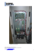
Typical Front View, Doors Closed Phone: (714) 970-2304 Fax: (714) 970-6171 Service: (714) 970-2304 (m-f, 8:00 – 5:00), after hours (951) 840-0811 Web Page: www.DSPManufacturing.com Email: sales@dspmanufacturing.
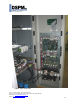
(Typical left hand view) Phone: (714) 970-2304 Fax: (714) 970-6171 Service: (714) 970-2304 (m-f, 8:00 – 5:00), after hours (951) 840-0811 Web Page: www.DSPManufacturing.com Email: sales@dspmanufacturing.
(Typical right hand view) Phone: (714) 970-2304 Fax: (714) 970-6171 Service: (714) 970-2304 (m-f, 8:00 – 5:00), after hours (951) 840-0811 Web Page: www.DSPManufacturing.com Email: sales@dspmanufacturing.
1-3 PRODUCT FEATURES The following describes the major sub-systems within the ETERNALIGHT 1 UPS. INPUT AND OUTPUT FILTER – The input filter reduces the input transients and harmonics on the input line. This helps protect the electronic circuitry of the UPS. The output filter filters and noise and line spikes from loads. INPUT POWER FACTOR CORRECTION - The ETERNALIGHT 1 UPS system includes state – of – the – art input power factor correction.
SECTION 2 – PREINSTALLATION 2-1 SITE PLANNING AND PREPARARTION The ETERNALIGHT 1 is designed for installation indoors where it is protected from the elements. The UPS can be installed in a variety of different environments including computer rooms, offices, and industrial/process control locations. For the best performance and reliability, temperature extremes should be avoided. Listed below are the environmental specifications for the ETERNALIGHT 1 UPS SYSTEM.
Eternalight 1 Emergency Lighting Inverter KWatts Input Voltage 120 208 5.25 240 277 480 120 208 7 240 277 480 120 208 9 240 277 480 Output Voltage 120 240 277 120 240 277 120 240 277 120 240 277 120 240 277 480 120 240 277 120 240 277 120 240 277 120 240 277 120 240 277 480 120 240 277 120 240 277 120 240 277 120 240 277 120 240 277 480 Utility Feed Max Output Amps Amps 88 51 44 38 22 117 68 59 51 30 150 87 75 65 38 43.7 21.8 18.9 43.7 21.8 18.9 43.7 21.8 18.9 43.7 21.
SECTION 3 – INSTALLATION The ETERNALIGHT 1 UPS system is shipped on a pallet with the batteries outside the UPS. This Manual, battery jumper wires and accessories may be included within the packaging, ensure that these are not discarded with the packaging. Unwrap the UPS and carefully inspect the external surfaces for abrasions, indentations, or other obvious damage. File a claim with the shipping agency for any damage caused by shipping. Forward a copy of the damage claim to DSPM.
DANGER!! THE UPS CONTAINS POTENTIALLY LETHAL VOLTAGES INSIDE, EVEN IF THE UNIT IS NOT CONNECTED TO AN EXTERNAL SOURCE OF POWER. ALL INSTALLATION AND SERVICE PROCEDURES SHOULD BE PERFORMED BY QUALIFIED PERSONNEL ONLY. The input power circuit is supplied by the customer. This provides power from the building source to the UPS system. This circuit should be a dedicated branch circuit that is hard wired in conduit. Size the branch circuit feeder conductors according to the specific power rating of the unit.
3-2 INPUT CONNECTIONS 1. Verify that power source to the unit is OFF, locked and tagged according to OSHA requirements. CAUTION Verify that the input voltage as stated on the UPS nameplate, matches the customer-supplied voltage. If the voltage does not match, STOP installation of the UPS and contact Customer Service at DSPM. 2. Verify that Input cable and conduit are routed correctly and are in position to 3. 4. 5. 6. 7. connect the unit.
(Input terminals blocks and breaker) 3-3 OUPUT CONNECTIONS 1. Verify that power source to the unit is OFF, locked and tagged according to OSHA requirements. CAUTION Verify that the output voltage as stated on the UPS nameplate matches the actual output voltage of the unit. Ensure that the intended connected load does not exceed unit capacity. If the voltage does not match, or the intended applied load exceeds unit capacity, STOP installation of the UPS and contact Customer Service at DSPM. 2.
Output Terminal Blocks Ground / Neutral / Hot 3-4 BATTERIES AND BATTERY CABLES WARNING!! FOLLOW THE BATTERY SAFETY PROCEDURE IN THE FRONT OF THIS MANUAL. The UPS system has fixed battery trays. All battery systems connect the batteries in series, i.e. plus terminal to minus terminal from one battery to another battery. The battery circuit breaker must be off during the installation. Install the batteries and connect the battery cables.
BATTERY SYSTEM TEST 1. Make sure A.C. input circuit breaker is OFF. 2. Make sure battery circuit breakers are OFF. 3. Use a meter and note the D.C. voltage at the battery circuit breaker. The voltage must be the correct polarity positive lead of the meter to the positive terminal of the circuit breaker. 4. The D.C. voltage should read between 220 to 240 VDC for an 18-battery unit and 118 to 130 for a 10-battery unit. If the D.C voltage reads below 210 volts D.C.
4-0 OPERATIONS 4-1 STARTING THE UPS 1. 2. 3. 4. 5. 6. 7. 8. 9. Check the input A.C. circuit breaker is OFF. Check all output circuit breaker(s) (optional) are OFF. Check the battery circuit breaker(s) are OFF. Energize the Utility feeder to the unit. Turn the Input circuit breaker ON. Wait for the System display message instructing you to close the battery breaker. Turn on the Battery Breaker. Wait for the System Display message stating unit is operational. Turn on the Output Breaker.
History Log Key: The History Log is used to record certain events that reflect the status and operating mode of the unit. There are 64 lines (00 through 63). It is read by holding down the Alarm Scan button. Each time the button is pressed, the log is read sequentially with the most recent event being displayed first. After 00 is displayed, the system will cycle around to 63. After 64 events are logged, the system will start recording again at 00.
43 45 46 47 49 50 51 52 53 54 56 57 58 WDTMR trap ISBS xfer Inv Stop Pwr on RST ESTOP trap RunState0 RunState1 RunState2 RunState3 Bypass on Battry Low KeyCode OK AirFlow DN Software has detected a Watchdog timer overflow Static Bypass Switch has transferred load to Inverter Inverter has unexpected shut off CPU initialization complete Emergency Stop option has caused an emergency transfer to utility Power has been applied to system Initial system checks complete, awaiting DC breaker closure Startup comple
4-2 TURNING THE UPS SYSTEM OFF 1. Turn OFF the output circuit breakers. 2. Turn OFF the input A.C. circuit breaker. 3. Turn OFF the battery circuit breaker. 4-2 OUTPUT POWER 1. Normally on circuits can be provided. These circuits are on when AC input power is on and turned off to lower the load requirements where input AC power fails. 2. Normally off circuits can be provided. These circuits provide power only when the UPS system is on battery power. These circuits usually power exits signs and lighting.
6.0 MAINTENANCE CAUTION: DO NOT DISPOSE OF BATTERIES IN FIRE CAUTION: DO NOT ATTEMPT TO OPEN THE BATTERIES CAUTION: THE FOLLOWING PRECAUTIONS SHOULD BE TAKEN WHEN REPLACING ANY BATTERIES • REMOVE WATCHES, RINGS, ETC… • USE TOOLS WITH INSULATED HANDLES. CAUTION: USE RUBBER PROTECTIVE GLOVES WHEN HANDLING DAMAGED BATTERIES. WARNING: HIGH VOLTAGE IS PRESENT ON BATTERIES. 1. Semi-annual i. Cabinet/Electronics 1. Inspect all fans and insure proper operation. ii. Batteries/Battery Cabinet 1.
e. Check wiring for proper routing and damage, such as chaffing and/or cutting. Relocate and /or repair and found damaged wires. f. Check the torque of each battery connection for 70in/lbs. CAUTION: DO NOT OVER TORQUE THESE CONNECTION AS SOME BATTERIES HAVE LEAD POSTS AND THEY ARE VERY EASY TO COMPRESS AND WILL CAUSE FAILURES IN THE FUTURE. Note: If Batteries are found to be leaking or fail the load test they should be replaced. (Consult DSPM as to the status of your Battery Warranty) 2.
2. Check the torque of each battery connection for 70in/lbs. CAUTION: DO NOT OVER TORQUE THESE CONNECTION AS SOME BATTERIES HAVE LEAD POSTS AND THEY ARE VERY EASY TO COMPRESS AND WILL CAUSE FAILURES IN THE FUTURE. Note: If Batteries are found to be leaking or fail the load test they should be replaced. (Consult DSPM as to the status of your Battery Warranty) 7.0 TROUBLE SHOOTING 7.0.1 If unable to resolve any problem please contact DSPM for assistance. DSPM Inc.