
Data Sheet


Version 2.2
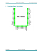
DHAN-T DECT-ULE Module
Pinout and Signal Description
April 16, 2020
DSP Group Confidential
7/17
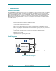
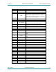
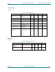
PIN NO.
NAME
DESCRIPTION/TYPE
1
GND
GND
2
ANT
Diversity Antenna. Leave unconnected
3
RSTN
For standalone operation, shunt this pin to GND with
100nF. For an application running on an external
MCU, this pin should be connected to a Host MCU
IO and used to reset the DHAN-T
4
DCINS
Leave as not connected (NC)
5
GPIO17
6
SCL (GPIO0)
GPIO or I2C Clock. Open Drain, reset value is
floating. Leave as not connected if not used
7
SDA (GPIO1)
GPIO or I2C Data. Open Drain, reset value is
floating. Leave as not connected if not used
8
GPIO2
GPIO or TDM_TXD
9
GPI03
GPIO or TDM_RXD
10
GPIO4
GPIO or TDM_FSYNC
11
GPIO5
GPIO or TDM_FSYNC
12
GPIO6
GPIO or SPI Data In. Leave as not connected if not
used
13
GPIO7
GPIO or SPI Data Out. Leave as not connected if not
used
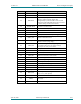
14
GPIO8
GPIO or SPI Clock
15
GPIO9
GPIO or UART Rx or SPI Chip Select
16
VCC_GPIO
Input. Sets the IO Logic level at the module interface
at 1.8 or 3V
17
USB_DM
18
USB_DP
19
TDI
JTAG Data In. Should be connected to TP
20
TDO
JTAG Data Out. Should be connected to TP
21
GND
22
TMS
JTAG Mode Select. Should be connected to TP
23
TCK
JTAG Clock. Should be connected to TP
24
RTCK
JTAG Reset. Should be connected to TP
25
GPIO10
GPIO or UART Rx or UART Tx
26
GPIO11
GPIO or UART Tx
27
GPIO12
GPIO
28
GPIO13
GPIO
29
GPIO14
GPIO
30
GPIO15
GPIO