Installation Guide Self Contained Wireless Alarm System v1.0 WARNING: This manual contains information on limitations regarding product use and function and information on the limitations as to liability of the manufacturer. The entire manual should be carefully read. WWW.DIYALARMFORUM.
SAFETY INSTRUCTIONS for SERVICE PERSONNEL WARNING: When using equipment connected to the TELEPHONE NETWORK, there are basic safety instructions that should always be followed. Refer to the SAFETY INTRUCTIONS provided with this product; save them for (future) reference. Instruct the end-user regarding the safety precautions that shall be observed when operating this equipment.
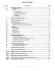
Table of Contents Section Description Page 1 1.1 1.2 Installation & Wiring............................................................................................ 1 Installation ........................................................................................................ 2 Wiring ............................................................................................................... 3 1. Zone Wiring....................................................................................
WWW.DIYALARMFORUM.
Section 1: Installation & Wiring Section 1: Installation & Wiring This Installation Guide provides the basic installation, wiring and programming information for the PowerSeries Self Contained Wireless (SCW) Security System. This publication covers the following versions of the SCW Security System: SCW9045-433 v1.0 SCW9047-433 v1.0 SCW9045-868 v1.0 SCW9047-868 v1.
Self Contained Wireless Alarm System v1.0 1.1 Installation: 1 If required, separate the front and back covers by removing the cover screw then inserting a small slotted screw driver between the front and back covers and gently twist the screwdriver to separate. Figure 1, Opening Cover 2 Route Telephone line wiring, I/O Wiring, and AC power through a single or double ganged junction box and through cutout in the back cover see Fig. 2 Mounting & Wiring details. If Programming with DLS, See “4.
1.2 Wiring 1.2 Wiring 1. Zone Wiring Zones can be wired for Normally Open, Normally Closed Contacts with Singleend-of-line (SEOL) resistors or Double End-of-Line (DEOL) resistors. Observe the following guidelines • • • • Normally Closed Loops - Do NOT use for UL Installations For UL/ULC listed installations use SEOL or DEOL only. Minimum 22 AWG wire, maximum 18 AWG Do NOT use shielded wire Wire run resistance shall not exceed 100Ω. Refer to the chart below.
Self Contained Wireless Alarm System v1.0 NOTE: Do not connect transformer to a receptacle controlled by a switch. For UL/ULC Installations use a Class 2, power limited, plug-in transformer 4 WWW.DIYALARMFORUM.
Section 2: Wireless Device Enrollment Section 2: Wireless Device Enrollment Before a wireless device can be recognized by the security system, it must be enrolled. Devices that are not enrolled will be ignored by the system. See “Section [904]: Wireless Module Placement Test” on page 44. Device Enrollment must be performed close to the alarm system. Maximum signal strength is required to ensure that the correct device is being enrolled. 1.
Self Contained Wireless Alarm System v1.0 If the installer attempts to enroll a device already on the system, the keypad will briefly indicate that it is a duplicate ESN. Place wireless detectors in the desired locations and perform the wireless placement test. Reposition devices if necessary to achieve the required signal strength. Zone Dependant Devices (Detectors) After the zone has been selected the keypad will display zone type 03. The Installer may enter an alternate zone type if required.
Section 3: Template Programming Section 3: Template Programming Template programming allows the Installer to quickly program the minimum functions required for basic operation. The installer is prompted to enter a 4-digit code that selects predefined zone definitions, reporting code formats, Troubles & Restorals, and DLS setup (see Digit 1 - 4 tables below).
Self Contained Wireless Alarm System v1.
Section 3: Template Programming Users OPENINGS, Residential Dial Reporting codes Section 1-8 11 12 13 14 15 16 17 18 [342] 9-16 21 22 23 24 25 26 27 28 [342] 40 98 FF XX XX XX XX XX XX [344] Enable Opening/Closings call directions for Phone 2 [367]Opt 2 ON FF=Communicates in Automatic Mode, XX=Not Used • Installer Lead-in/Lead-out and DLS Lead-in/Lead-out DLS Lead In DLS Lead Out Sect [347] Opt 4 Sect [347] Opt 5 Installer Lead Out Installer Lead In Sect [347] Opt
Self Contained Wireless Alarm System v1.0 Section 4: DLS Programming 4.1 Local Programming with PC-Link Follow the steps below in the sequence indicated to set up local programming using DLS: New Installations (Refer to section 1.1 Installation on page 2) 1. Connect the AC Wiring before mounting the back plate. In a new installation the backup battery requires 24 Hrs. charging. AC Power is required for PC-Link Programming until battery is charged. 2. Secure the front cover to the backplate 3.
Section 5: Operation Section 5: Operation The LCD keypad displays the description and status indicator lights represent alarm functions and status. This section describes basic keypad commands. Refer to the User Guide for detailed descriptions of all keypad commands. Press the [#] key to reset the keypad if an error has been made entering user codes or keypad commands 5.1 – Away Arming The Ready light must be ON to arm the system.
Self Contained Wireless Alarm System v1.0 [ ][2] – Trouble Display Refer to Appendix E: Troubleshooting Guide, for troubleshooting assistance and a detailed description of all trouble conditions. [ ][3] – Alarm Memory Display Pressing the scroll <> keys will display an “Alarms in Memory” message if an alarm occurred during the last armed period. Pressing [ ][3] will display the message “Scroll to view Alarms”. Scrolling will display the zones that went into alarm.
Section 5: Operation [4] System Test: The panel will activate the keypad buzzer, LCD pixels and all keypad status lights for 2 seconds followed by 2 seconds of full volume alarm, then transmit a reporting code to the central station (if programmed). [5] Enable DLS: The panel will temporarily enable DLS double-call for 6 hours. [6] User Initiated DLS: The panel will attempt to call the DLS computer. [7] Future Use [8] User Walk Test Mode: The panel will switch into User Walk Test Mode.
Self Contained Wireless Alarm System v1.0 Section 6: Advanced Programming This section provides the information necessary to program all required features for a basic system as well as common applications. 6.1 How to Program: DSC recommends filling in the Programming Worksheet with the required programming information before programming the system. This will reduce the time required to program and will help eliminate errors. To enter Installer Programming press [ ][8][Installer Code].
Section 7: Programming Work Sheets Section 7: Programming Work Sheets 7.1 Index to Programming Work Sheets and Descriptions Programming Option.............................................................. PWS/Desc. Programming Option (cont.).................................................. PWS/Desc. [000] Keypad Function Key Programming....................................... 16/33 [001]-[002] Zone Definitions............................................................ 16/33 [005] System Times ..........
Self Contained Wireless Alarm System v1.0 7.2 Programming Worksheets Unless indicated otherwise, default values apply to NA, EU and CP-01 SIA FAR CP-01 defaults are indicated in gray text. EU Defaults are indicated by a Superscript EU e.g., ( EU ) or ( EU005) NA Defaults are indicated by a Superscript NA e.g., ( ) NA or ((NA005) Keypad and Function Key Programming See “Local Keypad Programming” on page 30. for additional options.
7.2 Programming Worksheets [005] System Times Valid entries for Entry Delay are between 030-255, valid entries for SIA CP-01 Exit Delay is between 045-255. I___I___I___I 030 045 120 004 Entry Delay 1 I_0_I_3_I_0_I Entry Delay 2 I_0_I_6_I_0_I Exit Delay I___I___I___I Bell Cut-off For SIA CP-01 compliant installations, the Exit Delay must be within the range of 045-255 seconds (Default 60 seconds).
Self Contained Wireless Alarm System v1.0 [014] Second System Options Opt ON OFF 1 Def. Arm/Disarm Bell Squawk Enabled Arm/Disarm Bell Squawk Disabled 2 Future Use 3 RF Jam Log After 5 Minutes RF Jam Logs After 20 seconds 4 Aux Boost Enabled Aux Boost Disabled 5 Future Use 6 Audible Exit With Urgency 7 Future Use 8 Fire Bell is Continuous Silent Exit Delay Fire Bell Follows Bell Cut-off [015] Third System Options Opt ON OFF 1 Def.
7.2 Programming Worksheets [030] Zone Loop Response Options Opt ON OFF 1 Zone 33 is Fast Loop Response Zone 33 is Normal Loop Response 2 Zone 34 is Fast Loop Response Zone 34 is Normal Loop Response 3-8 Def. Future Use [101]-[134] Zone Attributes (Options 10-13 are reserved for Future Use). Zone Attribute Defaults Attribute: 1 2 3 4 5 6 7 8 9 ON Audible Steady Chime Bypass Force* Swing Tx.
Self Contained Wireless Alarm System v1.
7.2 Programming Worksheets Reporting Codes All Reporting Codes are defaulted ‘FF’ unless indicated otherwise.
Self Contained Wireless Alarm System v1.
7.
Self Contained Wireless Alarm System v1.
7.2 Programming Worksheets [381] Second Communicator Options Opt Def.
Self Contained Wireless Alarm System v1.0 [406] Number of Rings To Answer On Default 000 Valid entries are 000-009, (000 to disable) I_______I_______I_______I [499] Initiate PC-Link Downloading Enter [499] [Installer Code][499] [501]-[502] PGM Output Attributes Program only the following attributes for the PGM options listed. All others will be ignored. PGM options are programmed in Section [009].
7.2 Programming Worksheets [600] 2-way Audio Control Options (Applies to SCW9047 only) Opt Def. ON OFF 1 Tampers Enabled Disabled 2 Openings & Closings Enabled Disabled 3 [A] Key Alarm Enabled Disabled 4 [P] Key Alarm Enabled Disabled 5 Duress Alarm Enabled (Listen) Disabled 6 Opening after Alarm Enabled Disabled *7 Bell Active during 2-way Audio Verification. Bell Silent during 2-way Audio Verification.
Self Contained Wireless Alarm System v1.
7.2 Programming Worksheets [82]-[85] Zone Transmitter Supervision [82] Opt Zone 1-8 Def. [83] Zones 9-16 [84] Def. Zones 17-24 Def. [85] Zones 25-32 Def.
Self Contained Wireless Alarm System v1.0 Local Keypad Programming Enter [ ] when in Installer Programming to Access Keypad programming [001]-[034] Label Programming (Zone 1-34) Default Zone Sub Sect. Z O N E _ _ _ _ X X _ _ _ _ Zone Sub Sect.
7.
Self Contained Wireless Alarm System v1.0 [074] First Keypad Options Opt Def. ON OFF 1 Future Use 2 [A] Key Enabled [A] Key Disabled 3 [P] Key Enabled [P] Key Disabled 4 Quick Arm Prompt ON Quick Arm Prompt OFF 5 Quick Exit Prompt ON Quick Exit Prompt OFF 6 Bypass Options Prompt ON Bypass Options Prompt OFF 7 User Initiated Call-up Prompt ON User Initiated Call-up Prompt OFF 8 Hold [P]anic Key Prompt ON Hold [P]anic Key Prompt OFF [075] Second Keypad Options Opt Def.
Section 8: Programming Descriptions Section 8: Programming Descriptions The following is a brief description of the features and options available in the control panel. Section [000] Keypad Function Key Programming The five function keys can be reprogrammed with following functions.
Self Contained Wireless Alarm System v1.0 [37] Night Zone: Functions like Interior Stay/Away (05) but will remain bypassed if the user presses [ ][1] to re-activate Stay/Away zones when armed in the Stay mode [87] Delayed 24-Hour Fire (Wireless): Instant audible alarm when violated, communication delayed 30 seconds. If the alarm is acknowledged during the time delay (by pressing a key), the alarm will be silenced for 90 seconds and then the cycle is repeated.
Section 8: Programming Descriptions Section [013] First System Options Option Description [1] ON: Hardwired Zone 33 enabled. OFF: PGM1 Output enabled. Program Zone Definition or PGM option in Section [009] [2] ON: Hardwired Zone 34 enabled. OFF: PGM2 Output enabled. Program Zone Definition or PGM option in Section [009] [3]-[5] Future Use [6] ON: Audible Exit Fault Enabled.
Self Contained Wireless Alarm System v1.0 [8] ON: System Tamper Enabled. The panel will monitor the physical tamper switch, if the system is taken off the wall, or the front housing is removed, a System Tamper Alarm will be generated. OFF: System Tamper Disabled: The panel will not monitor the physical tamper switch. Section [016] Fourth System Options Option Description [1] ON: Cross Zoning Enabled. The panel will use the Cross Zone Attribute for Burglary Verification. OFF: Police Code Enabled.
Section 8: Programming Descriptions Section [030] Zone Loop Response Options This section is used to determine the Loop Response Time for hardwired zones 33 and 34. ON: Fast Loop Response. The loop response time will be 36 mS. OFF: Normal Loop Response. The loop response time will be 400 mS. Section [101]-[134] Zone Attributes These sections are used to customize the operation of the zones. There are 12 toggle options in each Section: Option Description [1] Bell Options - ON: Audible.
Self Contained Wireless Alarm System v1.0 Section [170] PGM Output Timer Program the time, in seconds, PGM outputs programmed to follow the PGM Output Timer will activate for. Valid entries are [001] to [255]. Section [176] Cross Zone/Police Code Timer Program the time, in seconds (Cross Zone) or minutes (Police Code), that the panel will use to determine if a Cross Zone or Police Code event has occurred.
Section 8: Programming Descriptions Section [377] Communicator Variables Program a 3-digit number for each program entry: Swinger Shutdown (Alarms): Maximum number of alarm/restoral transmissions per zone. Valid entries: [000] to [014]. Program data [000] to disable shutdown. Swinger Shutdown (Tamper): Maximum number of tamper alarm/restoral transmissions per zone. Valid entries: [000] to [014]. Program data [000] to disable shutdown.
Self Contained Wireless Alarm System v1.0 Section [381] Second Communicator Options Option [1] Description ON: Opening After Alarm Keypad Ringback Enabled. When the Opening After Alarm reporting code is successfully transmitted to a programmed telephone number, the keypad will sound a series of 8 beeps to confirm to the end user that the Opening After Alarm Code was sent and received. This Ringback will occur for each Opening After Alarm code successfully reported.
Section 8: Programming Descriptions [4] ON: User Initiated Call-up Enabled. The user can initiate a downloading session using the [ ][6] command. OFF: User Initiated Call-up Disabled. The user cannot initiate a downloading session. [5] Future Use [6] ON: 300 Baud Panel Call-Up. When the user initiates a DLS connection, the panel will connect and send the initial header at 300 baud. OFF: 110 Baud Panel Call-Up.
Self Contained Wireless Alarm System v1.0 The following attributes are available for PGM Output Type [09] [1] ON: PGM output activates if a Service Required trouble condition is present. [2] ON: PGM output activates if an AC trouble condition is present. [3] ON: PGM output activates if a Telephone Line trouble condition is present. [4] ON: PGM output activates if a Failure to Communicate trouble condition is present. [5] ON: PGM output activates if a Zone Fault condition is present.
Section 8: Programming Descriptions Section [701] First International Options Option Description [1] ON: 50 Hz AC. Configures the system for 50Hz AC. OFF: 60 Hz AC. Configures the system for 60Hz AC [2] ON: Time Base Internal Crystal. The system uses the internal crystal for the internal panel clock. OFF: Time Base AC-Line. The system uses the AC frequency for the internal panel clock. [3] ON: AC/DC Arming Inhibit with Battery Check Enabled.
Self Contained Wireless Alarm System v1.0 Sub Section [82]-[85] Wireless Zone Supervision (Zones 1 - 32) Programming these sections determines whether or not the zone transmitter will be supervised. Panic Pendants do not send Supervisory signals and cannot be supervised. Sub Section [90] General Wireless Options (Zones 1 - 32) Option Description [1]-[6] Future Use [7] ON: RF Jam Disabled.RF Jam is disabled. OFF: RF Jam Enabled. RF Jam is enabled.
Section 8: Programming Descriptions Keypad Programming To access Keypad Programming enter [ ][8][Installer’s Code][ ]. To return to System Programming press [ ]. System Labels There are 39 programmable system labels which are programmable through the Keypad or Downloading. Once a label programming section has been entered, use the [<] and [>] Cursor keys to move left and right to get to another letter within the label.
Self Contained Wireless Alarm System v1.0 Section [074] First Keypad Options Option Description [1] Future Use [2] ON: [A] Key Enabled. When the [A] key is pressed and held, the keypad will generate a [A]ux key alarm. The display will prompt the user to hold the key. OFF: [A] Key Disabled. Prevents the keypad from requesting a [A]ux key alarm. [3] ON: [P] Key Enabled. When the [P] key is pressed and held, the keypad will generate a [P]anic key alarm.
Section 8: Programming Descriptions Section [076] Third Keypad Options Option Description [1] ON: Chime Enabled for Zone Openings. When the zone is open and the chime feature is enabled ([*][4] Door Chime), the keypad will chime the selected chime tone for the zone. OFF: Chime Disabled for Zone Openings. The keypad will not chime for zone openings [2] ON: Chime Enabled for Zone Closings.
Self Contained Wireless Alarm System v1.0 Section 9: Testing & Troubleshooting Testing: • • • • Power up system Program options as required (See Programming Section) Violate, then restore zones Verify correct Reporting Codes are sent to the Central Station Troubleshooting: • • • Power up system Enter ✱[2] to view Troubles Perform actions indicated in the tables below.
Section 9: Testing & Troubleshooting Trouble [4] Failure to Communicate Panel fails to communicate one or more events to central station Trouble [5] Zone Fault Press [5] to determine specific zones with a Fault trouble Hard-wired zone fault condition present.
Self Contained Wireless Alarm System v1.0 Appendix A: Reporting Code Formats The following tables contain Contact ID and Automatic SIA format reporting codes. See Programming Sections [320]-[348] for Reporting Codes Contact ID The first digit (in parentheses) will automatically be sent by the control. The second two digits are programmed to indicate specific information about the signal. For example, if zone 1 is an entry/exit point, you could program the event code as [34].
Appendix A: Reporting Code Formats Section # Dialer Direction* Automatic Contact ID Codes SIA Auto Rep Codes** Reporting Code Code Sent When...
Self Contained Wireless Alarm System v1.
Appendix B: Communicator Format Options 04 SIA FSK • SIA -0 is valid in Account or Rep Code (not 00 in a Reporting code though) • This format uses 300 Baud FSK as the communication media. The Account Code can be 4 or 6 hexadecimal digits in length, All reporting codes must be 2 digits in length. The SIA format will transmit a 4 (or 6) digit account code, a 2 digit identifier code and a 2 digit reporting code. The 2 digit identifier is pre programmed by the panel.
Self Contained Wireless Alarm System v1.
Appendix C: Regulatory Approvals Information SIA False Alarm Reduction Installations For a list of the defaults value programmed when the unit is shipped from the factory and for any other programming information refer to Appendix D: False Alarm Reduction. Caution Call Waiting Cancel (Section [382], Option 4) feature on a non-Call Waiting line will prevent successful communication to the supervising station.
Self Contained Wireless Alarm System v1.0 Appendix D: SIA False Alarm Reduction SIA Feature Programming Section Comments Range/Default Requirement Exit Time [005], 3rd entry Access to Entry and Exit delays and Bell Time Out for the system Range:45- 255 seconds Default: 60 sec.
Appendix E: 2-Way Audio Verification (SCW9047 only) Appendix E: 2-Way Audio Verification (SCW9047 only) The following information is intended for use by the Central Station Operator. The SCW9047 Audio Verification provides Talk and Listen-in capability for audio verification of alarms. This allows the central station to communicate with the occupants through the microphone and speaker of the alarm system.
Self Contained Wireless Alarm System v1.0 4. Initiating, Control and Termination of the Session: The Operator controls the session the using the following Audio Control Telephone Key Functions.To select the following commands, Press [*][0] followed by the key number(s) indicated below Key 0 1/4 Command Description Future Use Talk to Speaker Connects the monitoring station to the speaker .
NOTES: WWW.DIYALARMFORUM.
FCC COMPLIANCE STATEMENT CAUTION: Changes or modifications not expressly approved by Digital Security Controls could void your authority to use this equipment. This equipment has been tested and found to comply with the limits for a Class B digital device, pursuant to Part 15 of the FCC Rules. These limits are designed to provide reasonable protection against harmful interference in a residential installation.