
Installation guide


v
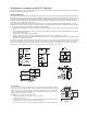
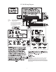
PC1404 Wiring Diagram
200–350 mA
93
1404
-11
2-WIRE AND 4-WIRE SMOKE DETECTORS
For NA
installations
only
1.2, 4, 7 Ah
LCD5511
LED5511
PC1555RKZ
PK5500/PK5501
PK5508/PK5516
PC1404RKZ/
PC1404RKZWH
PTK5507
US: F53AL01BPC1404
IC:160A-PC1404
(NA)
(EU)
24
5
FUSE 315mA/250V
(within terminal block)
ZONE DOUBLING
1500
BROWN
GREEN
RED
GOLD
2400
RED
YELLOW
RED
GOLD
-
-
2200 Ohm
END-OF-LINE
RESISTOR
EOLR-3
RM-1/RM-2 POWER LOOP
SUPERVISORY RELAY
EOLR-2
END-OF-LINE
RESISTOR
5600 Ohm, 0.5W
ALARM
INITIATING
LOOP
RESISTANCE
100 Ohm
12V
DC
o
.
can be used
-
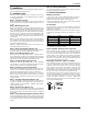
WARNING: Incorrect connections may result in PTC failure or improper
operation. Inspect wiring and ensure connections are correct before
applying power.
Incorrect connection of batteries may result in battery rupture or re
hazard. Do NOT allow metal objects to connect the positive and negative
terminals. Ensure that batteries are connected with correct polarity [Red to
(+), Black to (-)]. Failure to comply with this may result in battery rupture
and/or re hazard.
Note: It is the installer’s responsibility
to ensure that the external PRIMARY
wires are tied together using a cable
tie or equivalent as close as possible
to the terminal block.
30
CON1
BAT+BAT-
RED
BLK
so sI
1
-
to +55
(14
F
to 131
F)
Use a Class 2 Transformer
16.5V
AC 40 VA DSC PTD 1640U.
DO not connect transformer to receptacle
controlled by a switch.
T-1
R-1
TIP
RING
RJ-31X
RED
GRN
BRN
GRA
Telephone line wiring