PC1404 v1.0 Installation Guide WARNING: This manual contains information on limitations regarding product use and function and information on the limitations as to liability of the manufacturer. The entire manual should be carefully read.
6$)(7< ,16758&7,216 IRU 6(59,&( 3(56211(/ WARNING: When using equipment connected to the TELEPHONE NETWORK, there are basic safety instructions that should always be followed. Refer to the SAFETY INSTRUCTIONS provided with this product; save them for (future) reference. Instruct the end-user regarding the safety precautions that shall be observed when operating this equipment.
*XLGHOLQHV IRU /RFDWLQJ 6PRNH &2 'HWHFWRUV The following information is for general guidance only and it is recommended that local fire codes and regulations be consulted when locating and installing smoke and CO alarms. 6PRNH 'HWHFWRUV Research indicates that all hostile fires in homes generate smoke to a greater or lesser extent. Detectable quantities of smoke precede detectable levels of heat in most cases. Smoke alarms should be installed outside of each sleeping area and on each storey of the home.
Limited Warranty Digital Security Controls warrants the original purchaser that for a period of twelve months from the date of purchase, the product shall be free of defects in materials and workmanship under normal use. During the warranty period, Digital Security Controls shall, at its option, repair or replace any defective product upon return of the product to its factory, at no charge for labour and materials.
Table of Contents Safety Instructions for Service Personnel . . . . . . . . . . . . . . . . . . . . . . . . . . . . . . . . . . . . . . . . . . . . . . . . . . . . . . . . . . . . . . . . . . . . . . . . . . i 1 Introduction . . . . . . . . . . . . . . . . . . . . . . . . . . . . . . . . . . . . . . . . . . . . . . . . . . . . . . . . . . 1 1.1 Compatibility Requirements. . . . . . . . . . . . . . . . . . . . . . . . . . . . . . . . . . . . . . . . . . . . . . . . . . . . . . . . . . . . . . . . . . . . .
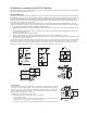
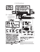
PC1404 Wiring Diagram so sI . - - 1.2, 4, 7 Ah CON1 BAT+BAT- 200–350 mA BLK For NA installations only RED T-1 R-1 TIP RING Use a Class 2 Transformer 16.5VAC 40 VA DSC PTD 1640U. DO not connect transformer to receptacle (NA) controlled by a switch. BRN Telephone line wiring GRA GRN RED RJ-31X 30 Note: It is the installer’s responsibility to ensure that the external PRIMARY (EU) 24 wires are tied together using a cable 5 tie or equivalent as close as possible to the terminal block.
1 Introduction 1 Introduction This manual provides installation and programming information for the PC1404 four-zone panel security system. 1.1 Compatibility Requirements The PC1404 product is the central component of the four-zone security system. Interaction with associated system devices is hardwired, which follows DSC keybus standards. Communications with the central station may be achieved by a hardwired phone line.
PC1404 Zone Configuration Operating Environmental Conditions • 31 zone types and 11 programmable zone attributes • Supports up to 4 hardwired NC, SEOL, DEOL zones, expandable to 8 with the zone doubling feature • Keypad zones allow the system to be configured to support 8 zones—4 onboard zones and up to 4 keypad zones • Temperature range: -10°C to +55°C (14°F-131°F) • Relative humidity: 93% noncondensing Access Codes • Supports 39 user codes and 1 master code • 6 programmable user code attributes; see
2 Installation 2 Installation The following sections provide a thorough description of how to wire and configure devices and zones. 2.1 Installation Steps Read this section completely before you begin. Once you have an overall understanding of the installation process, carefully work through each step. Step 1: Creating a Layout Draw a rough sketch of the building to get an idea of where all alarm detection devices, keypads and other modules are to be located.
PC1404 Keybus Terminals – AUX+, AUX-, YEL, GRN The Keybus is used by the panel to communicate with modules and vice versa. Each module has four Keybus terminals that must be connected to the four Keybus terminals on the panel. For more information, see Section 2.4 Keybus Operation and Wiring. be maintained at all points between power limited and nonpower limited wiring and connections.
2 Installation 2.5 Current Ratings – Modules & Accessories In order for the PC1404 system to operate properly, the power output capabilities of the main control and the expansion devices must not be exceeded. Use the data presented below to ensure that no part of the system is overloaded, affecting its function. PC1404 (12 VDC) AUX+: 550mA: Subtract the listed rating for each keypad, expansion module and accessory connected to AUX+ or Keybus.
PC1404 Single End Of Line (EOL) Resistors (5600) To enable panel detection of single end of line resistors, Section [013], Options [1] and [2] must be OFF. 2.10 Zone Doubling Zone Doubling is a feature that will allow you to double the zones on the main board from 4 to 8. To enable zone doubling, Section 13 Option [7] must be ON. All zones must be wired according to the following diagram. Only Normally Closed devices can be used with zone doubling. Zone input COM Wire A Wire B RZ1 RZ5 RE1 RE5 N.C.
2 Installation 2.11 Fire Zone Wiring 2.13 Keypad Zones All 4-wire smoke detectors must be wired according to the following diagram: Each “z” keypad on the system has a zone input to which a device - such as a door contact - can be connected. This eliminates the need to run wires back to the control panel for every device. To install the keypad, open the keypad plastic at the bottom of the unit. Locate the five terminals on the keypad circuit board.
PC1404 3 Keypad Commands Use any compatible keypad to enter commands and/or program the PC1404 security system. The LED keypad uses function and zone indicator lights to represent alarm functions and status. The LCD keypad provides a written description on the liquid crystal display and uses function indicator lights to communicate alarm status to the user. The PC1404 User Manual provides basic directions for arming and disarming the system, bypassing zones and performing user functions from the keypads.
3 Keypad Commands [ ][7][x] [ ][8][Installer Code] [ ][9][User Code] [ ][0] Command Functions 1–4 Installer Programming No-Entry Arming Quick Arm (disarmed state)/Quick Exit (armed state) [*][1] Bypassing and Activating Stay/Away and Night Zones LED Keypad Press [ ][1] to enter the bypass mode. If the Code Required for the Bypass option is enabled, enter a valid user code. The Bypass light will flash. The keypad will turn ON the corresponding zone light to indicate a zone is bypassed.
PC1404 Light Trouble 2 AC Failure: There is no audible annunciation on AC power failure unless trouble beeps on AC failure are enabled in 3 4 5 6 Section [018] Option [8]. The system "Trouble" light will come ON but the audible indication will not sound until there is a low battery condition. Transmission delay can be programmed for 000 to 255 minutes/hours. If the AC Fails, the battery will be continuously checked until the panel shuts down.
3 Keypad Commands [7] Bell Squawk upon Arming/Disarming – This attribute is used to determine whether an access code should generate an arming/disarming bell squawk at the end of exit delay. The attribute is off at default for all access codes, and this feature is meant to be used when Bell Squawk on Arming/Disarming is disabled in Section [014]. However, if the away function key is pressed on the system keypad, followed by an access code with this attribute enabled, the bell will still squawk.
PC1404 Additional Keypad Functions The following additional keypad functions are available: Event Buffer: Brightness Control: Contrast Control: Buzzer Control: View the 128-event panel buffer Adjust the display backlighting level for optimal viewing Adjust the display contrast level for optimal viewing Adjust the keypad buzzer tone for optimal sound [*][7] – Command Outputs When armed or disarmed, press [*][7] followed by the command output number 1 to 4.
4 Programming 4 Programming The PC1404 can be programmed using the following methods: Programming Method Description Procedure Installer Programming Allows direct access to all programming sections. Press [ ][8][Installer’s Code] while the system is disarmed. See 4.1 Installer Programming for details. DLS Programming Allows programming to be downloaded using DLS-IV™ software. DLS programming can be performed locally with a PC-Link cable and a PC with DLS-IV software installed.
PC1404 If you are using a pulse communications format, a decimal zero [0] does not transmit. Programming a zero [0] tells the panel not to send any pulses for that digit. Decimal zero [0] is a filler digit. To transmit a zero [0], it must be programmed as a Hexadecimal ‘A’.
5 Programming Worksheets 5 Programming Worksheets 5.1 Index to Programming Worksheets and Descriptions Programming Option PWS/Desc. [000] Keypad Function Key Programming ................ 16/34 [001] Zone Definitions............................................... 16/35 [005] System Times .................................................. 17/38 [006] Installer Code................................................... 17/38 [007] Master Code ....................................................
PC1404 5.2 Programming Worksheets Keypad Partition/Slot and Function Key Programming [000] Function Key Programming Note: Keypad enrollment must be done at each keypad requiring programming. Function keys are programmable in each individual keypad. The keypad being programmed must be used to access Installer Programming, followed by Section [000] and digits 1-5 for function keys 1 to 5. [0] Slot address For the partition, 0-8; for the slot, 1-8.
5 Programming Worksheets [005] System Times Valid entries for Entry Delay are between 030-255. Valid entries for SIA CP-01 Exit Delay are between 045-255.
PC1404 [011] PC5204 PGM Output Programming Default 01 I_______I_______I PGM 11 01 I_______I_______I PGM 12 01 I_______I_______I PGM 13 01 I_______I_______I PGM 14 [012] Keypad Lockout Options Note: If Keypad Lockout is active, the panel CANNOT be disarmed with a keyswitch.
5 Programming Worksheets 5 6 7 8 Keypad Backlighting Enabled Power Save Mode Enabled Bypass Status Displayed While Armed Keypad Tampers Enabled Keypad Backlighting Disabled Power Save Mode Disabled Bypass Status Not Displayed While Armed Keypad Tampers Disabled [017] Fifth System Options Opt. Def.
PC1404 Trouble Beeps are Silent Keyswitch Arms In Away Mode Only 7 8 Trouble Beeps Sound Every 10 seconds Keyswitch Arms In Stay or Away Modes [030] Zone Loop Response Options Opt Def.
5 Programming Worksheets Attribute: 9 10 =ON Cross Zn Zone Type: OFF 11 12 13 14 Zone Attributes 10-13 for Future Use 15 NC Loops No SEOL 16 DEOL Config. Config. Config. 00 Null Zone 01 Delay 1 02 Delay 2 03 Instant 04 Interior 05 Interior Stay/Away 06 Delay Stay/Away 07 Delay 24-hr. Fire (Hardwired) 08 Stand 24-hr. Fire (Hardwired) 09 24-hr. Supervisory (Hardwired) 10 24-hr. Supervisory Buzzer 11 24-hr. Burglary 12 Not Used 13 24-hr. Gas 14 24-hr. Heat 15 24-hr. Medical 16 24-hr.
PC1404 [176] Cross Zone/Police Code Timer Default 060 Valid entries are 000-255 seconds/minutes I_______I_______I_______I [181] Auto-Arm Time of Day Default 99:99 Valid entries are 0000-2359 hrs, 9999 to disable I_______I_______I_______I_______I [190] No Activity Arming Pre-alert Timer Default 001 Valid entries are 001-255 minutes, 000 for no pre-alert I_______I_______I_______I [191] System No Activity Arming Timer Default 000 Valid entries are 001-255 minutes, 000 to disable I_______I_______I__
5 Programming Worksheets [329] Priority Alarm and Restore Reporting Codes |___|___| Keypad [F] Fire Alarm |___|___| Keypad [A] Auxiliary Alarm |___|___| Keypad [P] Panic Alarm |___|___| Auxiliary Input Alarm |___|___| Keypad [F] Fire Restore |___|___| Keypad [A] Auxiliary Restore |___|___| Keypad [P] Panic Restore |___|___| Auxiliary Input Restore [330] Tamper Reporting Codes, Zones 01-08 Section [330] Zone 01 |___|___| Zone 02 |___|___| Zone 03 |___|___| Zone 04 |___|___| Zone 05 |___
PC1404 [343] Opening (Disarming) Reporting Codes, Access Codes 17-32 Code 17 |___|___| Code 25 |___|___| Code 18 |___|___| Code 26 |___|___| Code 19 |___|___| Code 27 |___|___| Code 20 |___|___| Code 28 |___|___| Code 21 |___|___| Code 29 |___|___| Code 22 |___|___| Code 30 |___|___| Code 23 |___|___| Code 31 |___|___| Code 24 |___|___| Code 32 |___|___| [344] Miscellaneous Opening (Disarming) Reporting Codes |___|___| |___|___| |___|___| |___|___| For Future Use For Future Use For Future Use For
5 Programming Worksheets [367] Opening/Closing Communicator Call Directions Option 1 First Telephone Number (Default OFF) Option 2 Second Telephone Number (Default OFF) Option 3 Option 4 Third Telephone Fourth Telephone Number (Default OFF) Number (Default OFF) Option 5-8 Future Use (Default OFF) [375] System Maintenance Alarm/Restore Communicator Call Directions Option 1 First Telephone Number (Default ON) Option 2 Second Telephone Number (Default OFF) Option 3 Option 4 Third Te
PC1404 3 SIA Sends Programmed Reporting Codes SIA Sends Automatic Reporting Codes 4 Closing Confirmation Enabled Closing Confirmation Disabled For Future Use 7 Contact ID Uses Programmed Reporting Codes Contact ID Uses Automatic Reporting Codes 8 For Future Use 5-6 [382] Third Communicator Options Opt. Def.
5 Programming Worksheets [404] Panel ID Code (Enter 6 Hexadecimal Digits) |_______|_______|_______|_______|_______|_______| Default = 140400 [405] Answering Machine Double-Call Timer Default 060 I_______I_______I_______I Valid entries are 000-255 seconds [406] Number of Rings To Answer On Default 000 I_______I_______I_______I Valid entries are 000-255 rings [501]-[514] PGM Output Attributes Program only the following attributes for the PGM options listed. All others are ignored.
PC1404 1 PGM Option 27 28 29 30 2 3 4 5 6 7 8 =ON Not Used Not Used True Output Follows Timer Code Req. Not Used Not Used Not Used – OFF – Inverted No Code No No No Notes: 1 Attribute: ON OFF ON/OFF Police Code For Future Use Zone Follower Status Alarm Memory A change of default setting will NOT affect the output. A change of default setting will affect the output. 2 Service Req.
5 Programming Worksheets Section Number Output Number Zone Follower Zone PC5204 [561] PGM 11 [562] PGM 12 [563] PGM 13 [564] PGM 14 [601] Closing (Arming) Reporting Codes, Access Codes 33-40 Code 33 |___|___| Code 34 |___|___| Code 35 |___|___| Code 36 |___|___| Code 37 |___|___| Code 38 |___|___| Code 39 |___|___| Code 40 |___|___| Code 39 |___|___| Code 40 |___|___| [605] Opening (Disarming) Reporting Codes, Access Codes 33-40 Code 33 |___|___| Code 34 |___|___| Code 35 |___|___|
PC1404 Programming PK5500 Keypads If you have an PK5500 keypad, additional programming is required for proper operation. All LCD programming is done per keypad. If more than one LCD keypad is present on the system, labels programmed at one keypad can be broadcast to all other LCD keypads. The following is a description of the available programming options and their accompanying programming sections: How to Enter LCD Programming Programming LCD keypads is similar to programming the rest of the system.
Programming PK5500 Keypads [001]-[008] Zone Labels Default Z o n e _ _ _ _ 1 _ _ _ _ _ _ _ _ _ _ _ _ _ _ _ _ _ _ _ _BBBB_BBBB_BBBB_BBBB_BBBB_BBBB_BBBB_BBBB_BBBB_BBBB_BBBB_BBBB_BBBB_BBBB_ _BBBB_BBBB_BBBB_BBBB_BBBB_BBBB_BBBB_BBBB_BBBB_BBBB_BBBB_BBBB_BBBB_BBBB_ Default Z o n e _ _ _ _ _ 8 _ _ _ _ _ _ _ _ _ _ _ _ _ _ _ _ _ _ [065] Fire Alarm Label _BBBB_BBBB_BBBB_BBBB_BBBB_BBBB_BBBB_BBBB_BBBB_BBBB_BBBB_BBBB_BBBB_BBBB_ _BBBB_BBBB_BBBB_BBBB_BBBB_BBBB_BBBB_BBBB_BBBB_BBBB_BBBB_BBBB_BBBB_BBBB_ Default F i
PC1404 [072] Second User Display Mask Opt 1 Def.
Programming PK5500 Keypads [080] PGM Terminal 1 Default 01 |_____|_____| PGM Output Number [082] Local PGM Output Activation Time Default 00 |_____|_____| Minutes 05 |_____|_____| Seconds [101] Partition 1 Label Default |____|____|____|____|____|____|____|____|____|____|____|____|____|____| S y s t e m _ _ _ _ _ _ _ _ _ _ _ _ _ _ _ _ _ _ _ _ _ _ |____|____|____|____|____|____|____|____|____|____|____|____|____|____| [102]–[108] Partition 2–8 Labels Default |____|____|____|____|____|____|____|____
PC1404 5.3 Programming Descriptions 3URJUDPPLQJ 'HVFULSWLRQV The following is a description of the programming features and options available in the control panel. [000] Keypad Function Programming Function Key Description [00] Null The key is not used and will perform no function when pressed. [01]-[02] Not Used [03] Stay Arm Arms the partition to which the keypad is assigned. All stay/away and night type zones will be automatically bypassed. Delay type zones will provide entry and exit delay.
5.3 Programming Descriptions [25] Instant Stay Arming This function key was formerly used for Recall Bypass Group 2. This feature operates similarly to the stay arming function key except for the following: When this function key is pressed, no acknowledgement beeps are sounded, there is no exit delay; and the system arms immediately. The panel logs "Armed in Stay Mode" for this closing type. If no stay/away zone types are programmed, the system arms in Away mode with no exit delay.
PC1404 [08] Standard 24-hr Fire Zone (hardwired) Note: Do not wire Fire zones on keypad zone terminals if the DEOL supervision option is enabled for the panel (Section [013], Option [2]). This zone type requires a SEOL resistor, and it cannot be reconfigured using the NC, EOL or DEOL options in the panel. The alarm state is short, the restored state is 5k6, and an open condition will generate a zone tamper and fire trouble.
5.3 Programming Descriptions A bypass of this zone type must be manually removed. With an audible alarm active, using the keyswitch when disarmed is the same as entering an access code at the keypad. Activating this zone type during the first 30 seconds of a delayed fire alarm is the same as entering an access code at the keypad (the 90 second delay will start). If left in the violated state, the system will not arm until the zone is restored and violated again.
PC1404 [005] System Times Enter Section [005] then Subsection [01] to program the Entry Delay 1, Entry Delay 2 and Exit Delay for the system. Entries are in seconds. A value of 000 in the entry or exit delay sections causes a 255 second delay; however, the time is displayed as 000. Enter Section [005] then Subsection [09] to program the Bell Cut-Off Time. Valid entries are in minutes. A value of 000 in the BTO section produces a 1 minute bell cut-off time. However, this time is displayed as 000.
5.3 Programming Descriptions PGM Output Options 09 System Trouble. This PGM output switches to ground when any of the selected Troubles are detected. The output de-activates when all of the selected Troubles are restored. The PGM attributes for this output are unique for this PGM type and the standard attributes do not apply. The PGM attributes for this output are as follows: 1 Service Required* 5 Fire Trouble/Zone Fault 2 A.C.
PC1404 PGM Output Options 19 Command Output #1. This output is activated by entering the [*][7][1] command. The configuration of the corresponding attributes determines how this PGM will activate. Command outputs 1-4 are user initiated by entering [*][7][1-4] at any keypad. When any output is activated, three ack beeps will be sounded by the keypad. This feature is User controlled. This function can be performed when a Programmable Output is programmed as Type [19].
5.3 Programming Descriptions [013] First System Options Option Description [1] ON: Normally Closed Loops. All zones are wired as normally closed circuits with returns connected to a COM terminal. The end-of-line resistor is not required. An alarm will be generated when the circuit is opened. OFF: End-of-Line Resistors. All zones must be wired with an end-of-line resistor configuration, determined by Option 2 in Section [013].
PC1404 [7] Exit Delay Termination Enabled. The exit delay will be reduced to 5 seconds when the system detects that a delay 1 zone Exit has been restored during exit delay. All audible indications associated with the exit delay (keypad tones, bell squawks) will Delay be silenced when the exit delay is reduced and terminates. Force armable delay 1 zones will still cause the exit delay to be Terminareduced if they restore during the exit period. tion Exit Delay Termination Disabled.
5.3 Programming Descriptions [3] ON: Blank Keypad When Not Used. If no keys are pressed for 30 seconds, the display and all keypad lights except backlighting (if enabled) turn OFF until the next keypress, entry delay, audible alarm, or keypad buzzer condition. Keypad function and FAP keys still operate during keypad blanking. OFF: Keypad Always Active. The keypad lights remain ON at all times. [4] ON: Access Code required to remove Keypad Blanking.
PC1404 [6] Cross Zoning/ Police Code ON: Cross Zoning is Enabled. The panel will use the Cross Zone attribute for Burglary Verification. This feature requires two or more trips from a zone that has the Cross Zone attribute enabled within a specified time before starting an alarm sequence. When a zone with cross zoning enabled is violated, no alarm occurs on the system; however, entry delay may start or the system event PGM may activate. The cross zoning timer will be started.
5.3 Programming Descriptions [030] Zone Loop Response Options Fast loop response for the onboard zones is programmable using Installer Programming Section [030]. Section [030] is an 8 bit toggle option that controls which main board zones will use fast loop response (~40mS) or normal loop response (~250mS). Note: Fast loop response should not be enabled for zones that are "doubled" by using the zone doubler feature.
PC1404 [168] Daylight Savings Time Begins Month [001] to [012] represents January to December. Week [000] indicates that the day of the month is programmed in the Day section below. [001] to [005] represents weeks 1 to 5 of the month. Week 5 always represents the last week in the month, regardless of whether the number of weeks in the month is 4 or 5. Day [001] to [031] represents the day of the month if [000] was programmed in the Week section above.
5.3 Programming Descriptions [199] Auto-Arming Pre-Alert Timer In this section, program the time (in minutes) for the Auto-Arming Pre-Alert time. This timer is used for all programmed auto-arming features (it is not used for no-activity arming). The keypads will provide a steady tone, warning the user that the system is preparing to arm. The user can enter a valid access code, or valid disarming procedure, to abort the arming sequence. Valid entries are 001 to 255.
PC1404 [330]-[334] Tamper/Restore Reporting Codes, Zones 01-8 These reporting codes are used by the communicator to transmit zone tampers and restores for Zones 1 to 8. These reporting codes are sent to the Tamper Alarm & Tamper Restore call direction group of the system. [338] Miscellaneous Tamper Reporting Codes General System Tamper & Restore These reporting codes are sent to the system Tamper Alarm & Tamper Restore call direction group when a panel tamper occurs.
5.3 Programming Descriptions Fire Trouble & Restore An open circuit or any Low Sensitivity, Tamper or Fault report from a wireless smoke detector causes this trouble to be reported. These reporting codes are sent to the System Maintenance call direction group. Auxiliary Power Supply Trouble & Restore If an auxiliary voltage supply trouble occurs (the Aux PTC has caused the auxiliary supply to stop outputting power), this trouble is reported.
PC1404 [348] Test Transmission Reporting Codes Walk Test Begin/End These reporting codes are sent when the walk test is initiated and terminated. These codes precede and terminate the alarm reporting codes for the zones that are activated during the walk test period, if the alarms are to be transmitted (Section [382] Option [2]). The walk test reporting codes are sent to the System Test Transmission call direction group.
5.3 Programming Descriptions [9] Delinquency Transmission Delay: Number of hours (Activity Delinquency) or days (Arming Delinquency) the panel delays before transmitting the event to the central station. Whether this value is in hours or days is determined if Delinquency is for Activity (Hours) or Closing (Days) as specified in Section [380] Option 8. The timer starts under the following conditions: 1. When the system is armed in Stay Mode; 2. When the system is disarmed; 3.
PC1404 [381] Second Communicator Options Option Description [1] ON: Opening After Alarm Keypad Ringback Enabled. When the Opening After Alarm reporting code is successfully transmitted to the monitoring station, the keypad sounds a series of 8 beeps to confirm to the end user that the Opening After Alarm Code was sent and received. This Ringback occurs for each Opening After Alarm code successfully reported. OFF: Opening After Alarm Ringback Disabled.
5.3 Programming Descriptions [7] ON: Number of Dialing Attempts is 1 for Residential Dial. If the residential dial format is programmed, the panel will only attempt to call the user's phone once. Regardless of whether the alarm is acknowledged by the end user by pressing a DTMF digit, the panel will not call back unless a new alarm has occurred. OFF: Residential Dialing Attempts is 5.
PC1404 [6] Baud Rate Selection ON: 300 Baud Call-up. 300 baud is the minimum baud rate used by 56K modems. When performing call-back or user initiated call-up with a 56K modem, this option should be enabled. OFF: 110 Baud Call-up. 110 baud is the supported baud rate for the MD-12 modem. When performing call-back or user initiated call-up with an MD-12, this toggle option should be disabled.
5.3 Programming Descriptions The following attributes are available for the System Trouble PGM Option [09]. System Trouble PGM (Type 09) [1] [2] [3] [4] [5] [6] [7] [8] Service Required A.C.
PC1404 [700] Automatic Clock Adjust The value entered here adds or subtracts seconds at the end of each day to compensate for inaccuracies in the system time. Valid entries are 00-99, with 60 seconds being the default. To determine the value to be programmed in this section, perform the following: 1. Monitor the time lost by the panel over a period of time. 2. Calculate the average amount of time per day the panel gains or loses. 3. Add or subtract this value (seconds) from 60 and enter the value.
5.3 Programming Descriptions [5] I.D. Tone ON: ID Tone Enabled. After the telephone number is dialed, the panel will emit a tone (as specified by Option 6). OFF: ID Tone Disabled. After the telephone number is dialled, the panel will not emit an I.D. Tone. [6] I.D. Tone Frequency ON: 2100 Hz I.D. Tone. After the telephone number is dialed, the panel will emit a 2100 Hz ID tone if enabled in Section [701] Option 5. OFF: 1300 Hz. ID Tone.
PC1404 [903] View Module Supervision In this mode, the system displays all of the modules presently enrolled on the system as indicated by the corresponding lights below: Indicator Light Module 1-8 Keypads 1-8 18 PC5208 19 PC5204 26-29 PC520X 1-4 [990] Installer Lockout Enable If enabled, the panel gives a distinctive audible indication on power-up (the phone line relay clicks 10 times). This feature has no effect on a software default (all programming will return to the factory defaults).
6 Testing & Troubleshooting 6 Testing & Troubleshooting Testing: • • • • Power up system Program options as required (see Section 5 Programming Worksheets) Violate, then restore zones Verify correct Reporting Codes are sent to the central station Troubleshooting: • • • Power up system Enter [ ][2] to view Troubles Perform actions indicated in the tables below Trouble Summary: Trouble [1] Service Required - Press [1] or for more information: 1 - Low Battery 2 - Bell Circuit Trouble 3 - General System
PC1404 Trouble Cause PC520X Aux Power Supply Trouble Troubleshooting • • [4] General System Tamper Tamper input on module(s) open circuit [5] Module Supervision Panel does not communicate with module(s) on KEYBUS Keypad assigned to incorrect slot [6] Not Used [7] PC520X Low Battery [8] PC520X AC Failure Ensure that a the power supply aux power terminal is not shorted to ground. Ensure that the maximum power supply aux current has not been exceeded.
6 Testing & Troubleshooting Trouble Cause Trouble [5] Zone Fault Troubleshooting Press [5] to determine specific zones with a Fault trouble Open circuit is present on one or more fire zones on the main panel or zone expander • • • An open circuit is present on PGM 2 being used as a 2-wire smoke detector input • • • A short circuit is present on one or more • zones with double end-of-line resistors enabled • Trouble [6] Zone Tamper Ensure fire zones have a 5.
PC1404 Appendix A: Reporting Code Formats The following tables contain Contact ID and Automatic SIA format reporting codes. See Programming Sections [320]-[348] for Reporting Codes. &RQWDFW ,' The first digit (in parentheses) is automatically sent by the control. The second two digits are programmed to indicate specific information about the signal. For example, if zone 1 is an entry/exit point, you could program the event code as [34].
Appendix A: Reporting Code Formats Table 1: Reporting Codes 6HFWLRQ 5HSRUWLQJ &RGH &RGH 6HQW :KHQ [345]-[346] Bell Circuit Trouble/Rest. 'LDOHU 'LUHFWLRQ [347] [347] [347] [347] Software deactivates the bell output if a short is detected MA/R so no additional current is taken from the battery./Bell output restored. Fire Trouble/Rest. Trouble occurs/restore on a fire zone MA/R 2-wire Smoke Trouble/Rest.
PC1404 Table 3: Automatic Zone Alarm/Restoral Codes =RQH 'HILQLWLRQ 6,$ $XWR 5HS &RGHV Delay 1 Delay 2 Instant Interior Interior Stay/Away Delay Stay/Away 24-Hr. Supervisory 24-Hr. Supervisory Buzzer 24-Hr. Burg 24-Hr. Gas 24-Hr. Heat 24-Hr. Medical 24-Hr. Panic 24-Hr. Emergency 24-Hr. Water 24-Hr.
Appendix B: Communicator Format Options Appendix B: Communicator Format Options The following format options are programmable in Section [350] Communicator Format Options 01 02 20 BPS, 1400 Hz handshake 20 BPS, 2300 Hz handshake • BPS Formats - 0 is not valid in Account or Rep Code (A must be used). Depending on the pulse format, the panel communicates using the following: 3/1, 3/2, 4/1 or 4/2, 1400 or 2300 Hz handshake, 20 bits per second, non-extended. Digit “0” sends no pulses and is used as a filler.
PC1404 06 Residential Dial If Residential Dial is programmed and an event that is programmed to communicate occurs, the panel will seize the line and dial the appropriate telephone number(s). Once the dialing is complete, the panel will emit an ID tone and wait for a handshake (press a 1, 2, 4, 5, 7, 8, 0, or # key from any telephone). It will wait for this handshake for the duration of Post Dial Wait for Handshake timer.
Appendix C: Regulatory Approvals Information Appendix C: Regulatory Approvals Information North America will provide advance notice in order for you to make necessary modifications to maintain uninterrupted service. FCC COMPLIANCE STATEMENT Equipment Maintenance Facility CAUTION: Changes or modifications not expressly approved by Digital Security Controls could void your authority to use this equipment.
Europe +HUHE\ '6& GHFODUHV WKDW WKLV GHYLFH LV LQ FRPSOLDQFH ZLWK WKH HVVHQWLDO UHTXLUHPHQWV DQG RWKHU UHOHYDQW SURYLVLRQV RI 'LUHFWLYH (& This product is in conformity with: 7KH FRPSOHWH 5 77( 'HFODUDWLRQ RI &RQIRUPLW\ FDQ EH IRXQG DW KWWS ZZZ GVF FRP OLVWLQJVBLQGH[ DVS[ EMC Directive 2004/108/EC based on results using harmonized standards in accordance with article 10(5), &=( '6& MDNR Y¿UREFH SURKODģXMH ŀH WHQWR Y¿UREHN MH Y VRXODGX VH YģHPL UHOHYDQW