p/n 7711011 Operator/Service Manual Rev.
Table of Contents Model Description page 3 Supplied Equipment page 3 Warranty Information page 3 Specifications page 4 Control Panel / Parts of the Centrifuge page 5 Setup Location page 6 Initial Setup Procedure pages 6,7 Operation page 7 Tube Holder Configurations Performance Plus Horizontal Rotor page 7 6-Place Horizontal Rotor page 8 6-Place Fixed Angle Rotor page 9 Control Panel Functions Time Adjustment and Timer Operation Speed Adjustment / RCF Display Starting and Stoppi
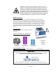
WARNING: For the safety of both the operator and service personnel, care should be taken when handling substances that are known to be toxic, radioactive or contaminated with pathogenic microorganisms when using this centrifuge. When Risk Group II materials are used (as identified in the World Health Organization “Laboratory Bio-Safety Manual”), a Bio-Seal should be employed. The rotor and rotor accessories should not be considered as Bio-Seals.
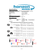
Specifications: General Specifications for the Horizon Model 842VES Centrifuge Overall Dimensions (H x W x D): 8.0 in. x 11.0 in. x 13.5 in. Centrifuge Motor: 1/2 H.P. Brushless DC Protection Breaker: 4 Amp. re–settable Timer: electronic, with hold or 0 to 99 minutes, +/- 1% Weight: 23 lbs.
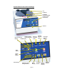
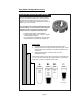
Control Panel / Parts of the Centrifuge: Lid Lid Knob Lid Safety Interlock System Control Panel (see below) Cabinet Up/Down RPM Change Buttons RCF Conversion Button RPM Display Latched Running Indicator Indicator Light Light Unlocked Indicator Light Start Button Open / Stop Button Time Display Up/Down Time Change Buttons Brake Display page 5 Program Memory Button Preset Display Memory Button
Setup Location: 1. Unpack the centrifuge and verify that all of the supplied equipment is present. 2. Choose a setup location which meets the following criteria: a) A bench top clearance height of 16” is required in order to open the lid. b) The clearance envelope is the space around the centrifuge which is required for safety. Choose a setup location which will allow for a clearance envelope of at least 24” x 24”, (with the centrifuge at the center).
Operation: NOTE: Follow the initial setup procedure before initial operation. 1. Press the ‘OPEN / STOP’ button to unlock the lid and then open the lid. 2. Insert cushions (if needed) into the tube carriers (holders) for the tube size you are using. Refer to ‘Tube Holder Configurations’ for assistance. 3. Place the test tube samples into the tube carriers (holders). Be sure to follow the rules for balanced loads. 4.
Tube Holder Configurations (cont.): Six (6) Place Horizontal Rotor (Standard): This rotor is designed to hold up to six (6) tube holders. It comes with two tube holder types. The purple holders are designed to hold tubes up to 10mL (up to 17mm x 100mm). The blue holders are designed to hold tubes up to 5mL (up to 17mm x 75mm). Your centrifuge must contain a balanced load in order to work properly.
Tube Holder Configurations (cont.): Six (6) Place Fixed-angle Rotor (optional): This rotor is designed to hold up to six (6) tube holders. It comes with three tube holder types. The orange holders are designed to hold tubes up to 15mL (up to 17mm x 125mm). The purple holders are designed to hold tubes up to 10mL (up to 17mm x 100mm). The blue holders are designed to hold tubes up to 5mL (up to 17mm x 75mm). Your centrifuge must contain a balanced load in order to work properly.
Control Panel Functions: Time Adjustment and Timer Operation - The run time may be set from 30 seconds to 99 minutes and 30 seconds. Press the up and down arrow buttons next to the time display to adjust the run time. Adjustments may be made prior to a run or after a run begins. A quick tap will adjust the time by 30 seconds. Hold down the button for 1 minute adjustments - continue to hold for 5 minute adjustments. Press the down button once while 00:30 is displayed to access the “hold” feature.
Advanced User Settings (continued): Braking Rate - The user may adjust the braking rate from minimum ( slowest deceleration, 0) to maximum (quickest deceleration, 9) using the following procedure: 1. While the centrifuge is idle, press the PROGRAM button. 2. Use the UP/DOWN arrow buttons next to the speed display until “BRAKE” is displayed in the speed display. 3. The current braking rate is displayed in the brake display.
Memory Locations / Storing and Recalling: The Performance Series centrifuges are capable of storing up to 10 user-defined presets. These memory presets contain all of the settings needed to define a specific run, (run time, speed, acceleration rate, braking rate, etc.). The user can use these memory locations to quickly configure the centrifuge for a specific test type and ensure that the test is run in the same way each time by recalling this same setting. Store a configuration in a memory location 1.
Care and Preventative Maintenance: With proper care and maintenance your Horizon centrifuge will provide years of laboratory service. For proper care, the following steps should be taken: 1. Provide Adequate Ventilation: For cooling purposes, the Horizon draws in ambient air through the air intake cover on the top of the lid and exhausts this air in the rear of the base. The centrifuge should be placed on a hard smooth surface for good air circulation. 2.
Rotor Removal and Installation: To remove the rotor: 1. Unlock the centrifuge by pushing the ‘OPEN / EMERGENCY STOP’ button and unlatch and open the lid. CAUTION: 1) Unplug the centrifuge from the electrical outlet at this time to eliminate the possibility of electrical shock or other injury. 2) Rotors may be removed for cleaning. However, rotors are not to be replaced in the field. The factory installed rotor is the only rotor intended to be used in the centrifuge. 2. 3. 4. 5.
Troubleshooting: 1. Problem: Solutions: 2. Problem: Solutions: 3. Problem: Solutions: The rotor does not spin freely. • Make sure that nothing has fallen into the rotor chamber. • If there is nothing obstructing the rotor, the motor may be damaged. Contact your authorized dealer or The Drucker Company for further assistance. There is excessive noise when the machine is running. • Check to see that the load is balanced.
Safety: The Horizon 842VES complies with all requirements of CE EN 61000-3-2, -3-3, EN 61000-4-2, -4-3, -4-4, -4-5, -4-6, -4-11, EN 61010-1, -2-020 and UL standard 3101–2–20, Can/CSA C22.2 No. 1010.1 , Can/CSA C22.2 No. 1010.2.20 Horizon Lid Safety Switch: The Horizon lid is secured to the top of the cabinet by a latching knob and pawl system. When the knob is rotated clockwise, the pawl grips the underside of the cabinet opening and prevents the lid from opening.
Contact your authorized dealer or The Drucker Company to order replacement parts or accessories. Replacement Parts: Part No. Description 7724177 Rubber Foot 7751068 Lid Tray Micro-Switch 7723002 Lid Tray Solenoid 7735011 Motor, ½ H.P.