SGS OWNER`S MANUAL WARNING: If the information in these instructions is not followed exactly, a fire or explosion may result causing property damage, personal injury or death. FOR YOUR SAFETY: Do not store or use gasoline or other flammable vapors and liquids in the vicinity of this or any other appliance. Installation and service must be performed by a qualified installer, service agency or the gas supplier. WHAT TO DO IF YOU SMELL GAS: • Do not try to light any appliance.
SGS GAS STOVES 1 TABLE OF CONTENTS GENERAL INFORMATION.................................................................................................................................................... 2 WARNINGS ........................................................................................................................................................................... 2 TECHNICAL SPECIFICATIONS .................................................................................................
SGS GAS STOVES 2 GENERAL INFORMATION The SGS GAS STOVE is a high-efficiency gas appliance with a maximum input rating of 28 500 BTU/h (8,4 kW) with natural gas or 26 000 BTU/h (7,6 kW) with propane. It features an adjustable millivolt valve and a constant pilot independent of any electrical source. Your appliance will therefore continue to heat your house in the event of a power failure. You can set the height of the flame to your liking by turning the adjusting knob.
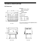
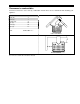
SGS GAS STOVES 3 TECHNICAL SPECIFICATIONS SGS Dimensions Dimensions Height : 27 3/4 po / 706 mm Width : 24 1/2 po / 621 mm Depth : 23 po / 585 mm Ceramic Glass 8 3/4 po x 16 5/8 po 222 mm x 422 mm Weight 115 lbs / 53 kg Color Metallic black Clearances to Combustibles • Back : 7 po 180 mm • Side : 7 po 180 mm • Corners : 4 po 100 mm • Top : 36 po 915 mm • Combustible Floor Note 1 TOP VIEW Note 1 : Your stove has been successfully certified while installed on a wood floor.
SGS GAS STOVES 4 SGS II Dimensions Dimensions Height : 27 3/4 po / 706 mm Width : 24 1/2 po / 621 mm Depth : 23 po / 585 mm Ceramic Glass Front : 11 1/2 po x 12 1/2 po 292 mm x 318 mm Side : 4 3/8 po x 12 1/2 po 111 mm x 318 mm Weight 122 lbs / 56 kg Color Metallic black Clearances to Combustibles • Back : 7 po 180 mm • Side : 7 po 180 mm • Corners : 4 po 100 mm • Top : 36 po 915 mm • Combustible Floor Note 1 Note 1 : Your stove has been successfully certified while installed on a wood floor.
SGS GAS STOVES 5 Burner Maximum Input, BTU/h (kW) Inlet Pressure Inch WC (kPa) Manifold Pressure Inch WC (kPa) Burner orifice, ∅ : minimum : maximum : minimum : maximum : minimum : maximum : Natural Gas 19 000 (5,6) 28 500 (8,4) 5,0 (1,3) 7,0 (1,8) 1,6 (0,4) 3,5 (0,9) #36 DMS Propane LP 20 000 (5,9) 26 000 (7,6) 11,0 (2,8) 14,0 (3,5) 6,3 (1,7) 10,0 (2,5) #52 DMS Gas Valve S.I.T. Controls USA Honeywell Natural Gas Model SIT 0.820.634 Nova mV VS8420E8001B Propane LP Model SIT 0.820.
SGS GAS STOVES 6 INSTALLATION Before starting any installation, make sure you know : • Where you run your gas line ; • What type of venting kit you need ; • Where you run your venting pipes ; • Where you install the terminal vent in respect with installation code ; • Clearances to combustibles ; • Length of horizontal and vertical runs of venting pipes. Safety Notice • • • • IMPROPER INSTALLATION MAY RESULT IN A HOUSE FIRE. FOLLOW INSTALLATION DIRECTIONS.
SGS GAS STOVES 7 Clearances to combustibles Clearance between the stove and any combustible material must also be maintained while installing your appliance. CLEARANCE Back (in) Side (in)) Corners (in) Top (in) Front (in) Pipe (in) Floor 7 7 4 36 36 1½ Combustible Note 1 Corner Installation Direct Installation Note 1 : Your stove has been successfully certified while installed on a wood floor. Do not install your stove on carpeted floor. Choose a ceramic tile or wood floor instead.
SGS GAS STOVES 8 Direct Vent Installation Critical Length of Venting Pipes The following table shows the maximum length to be respected while installing your appliance with venting pipes (4"X6 5/8") from Simpson DuraVent, Security Chimneys International (Secure Vent) or Selkirk (Direct-Temp) only. 30 29 28 27 The maximum number of elbows in your venting system is three (3) 45° elbows or one (1) 45° elbow and two (2) 90° elbows.
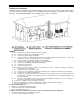
SGS GAS STOVES 9 Terminal Vent Location Your SGS stove vents through a vent terminal installed on the roof or on the outside of any exterior wall of your house. Many restrictions apply to the vent terminal location that should be considered before locating your stove. The following drawing presents a summary of most of these restrictions. LÉGENDE A. 12’’ B. 12’’ C. 12’’ D.
SGS GAS STOVES 10 Installation of Drolet Wall Venting Kits Direct And Corner Vent Kit Installation AC02000: Coaxial 4" X 6 5/8" rigid vent system with black finish includes : 1. 45° Elbow 2. 24" Pipe 3. 90° Elbow 4. 24" Pipe 5. Adjustable pipe 6. Wall thimble cover 7. Wall thimble 8. Snorkel termination cap Restrictor ring B Note: Restrictor ring B is supplied with your stove. Insert the ring between section 1 and 2. 1. Place the stove at the desired location ; 2.
SGS GAS STOVES 11 Direct Vent Kit for Basement Installation AC02010: Coaxial 4" X 6 5/8" rigid vent system with black finish includes : 1- 45° Elbow 2- Two 24" Pipes 3- 90° Elbow 4- 24" Pipe 5- Adjustable pipe 6- Wall thimble cover 7- Wall thimble 8- Snorkel termination cap Note: Restrictor ring B is supplied with your stove. Insert the ring between section 1 and 2. Restrictor ring B 1. Place the stove at the desired location ; 2.
SGS GAS STOVES 12 Vented Gas Stove Installation ("B-Vent") Instead of using a standard B-vent pipe it is possible to use a 4" flexible aluminum chimney lining system into an existing chimney. The existing chimney must be a code complying masonry or listed fuel burning chimney system: ‘B’ vent, ‘L’ vent UL103 or ULC S629. Refer to the installation standards in your area or CAN/CGA B149 AND ANSI Z223-1 standards (under "venting systems") and instructions of flexible pipe manufacturer.
SGS GAS STOVES 13 Stove conversion for a "B-Vent" installation only The following instructions are not for a direct vent installation. Your Drolet stove is coming to you ready for a direct vent installation. You can buy a conversion kit to be able to install it as a "B-Vent" unit. To convert your stove, just follow the instructions: 1. Remove the decorative panels (1) by unscrewing the two screws at the back of the stove. Simply slide the panel toward the front of the stove. 2.
SGS GAS STOVES 5. Remove and discard the metallic plate (6) from the rear heat shield using a screw driver. Unscrew just a little bit the two screws located each side of the chimney connector. Install the venting hood (5) by sliding it into place. Screw tightly in place. 6. Remove the four screws of the valve cover (7) and slide upwards to remove. 7. Unscrew the thermocouple (8) from the bottom of the valve to install interrupter bloc (9). Reinstall the thermocouple (8) into interrupter bloc (9).
SGS GAS STOVES 15 Gas Piping • Route a 3/8" minimum NPT iron pipe gas line to the desired location. • Install a shutoff valve to the gas line. Tighten securely using a pipe joint compound. • Check the gas line piping for leaks. Use a soap and water solution. CAUTION: DO NOT USE OPEN FLAME TO CHECK LEAKS. Logs Installation 1. Place the rear log (1) against the rear log holders. 3. Place log (4) on top of logs (1) and (2) in the Make sure grooves behind the log line up with the matching grooves. 4.
SGS GAS STOVES 16 Ember Kit Installation CAUTION: Blocking gas ports with rock wool will result in poor light-up performance, delayed ignition, affect flame aspect and form carbon deposit on logs. 1. Place some pieces of rock wool fibers approximately 1/2" large behind the front gas ports. 2. Light the stove. Modify the configuration of the rock wool near the gas ports until you reach the desired effect. Pedestal cover (model SGS and SGS II) 1.
SGS GAS STOVES 17 OPERATING YOUR STOVE For your safety ATTENTION : • A QUALIFIED INSTALLER MUST PERFORM INSTALLATION OF THE APPLIANCE, VENTING, PIPING AND ADJUSTMENTS. • DURING OPERATION, THIS STOVE IS HOT. DO NOT TOUCH. KEEP CHILDREN, CLOTHING, FURNITURE AND FLAMMABLE MATERIALS AWAY. • Make sure your stove is in good condition. Verify that the door close perfectly and that all controls work as per specifications. Vent must be in perfect condition and sealed.
SGS GAS STOVES 18 Shut down Instructions To turn the burner OFF but leave the pilot open • Push in and rotate the gas control knob clockwise 3 to "PILOT" position. Do not force. To turn the pilot OFF • Push in and rotate the gas control knob clockwise 3 to "OFF" position. Do not force. Optional Wall Thermostat (AC05558) Note: Use only a millivolt thermostat to prevent any permanent damage to the valve. The optional wall thermostat will automatically keep your room at an even temperature.
SGS GAS STOVES 19 The benefits of installing a blower A blower can be installed at the back of your DROLET stove. This option is necessary if you wish to redistribute into a room the heat trapped at the back of your stove. By forcing hot air toward the front, the blower enables you to extend the radiation power of your stove. You can purchase this option through your DROLET dealer. Make sure to specify this part number: #AC02050.
SGS GAS STOVES Optional Thermodisc (AC05530) Follow the installation instructions included with the optional thermodisc. The fixation holes are located at the back of the stove on the lower right corner. Refer to the drawing on this page. Note : The blower will start when the temperature at the back of the stove, where the air is circulated, reaches 110 O F (43 OC). This can take 30 to 60 minutes. The time varies depending of the burner intensity and the temperature of the room where the stove is located.
SGS GAS STOVES 21 MAINTENANCE INSTRUCTIONS WARNINGS : • TURN OFF THE GAS WITH THE SHUTDOWN VALVE AND DISCONNECT THE ELECTRICAL POWER BEFORE SERVICING THE APPLIANCE. • LABEL ALL WIRES PRIOR TO DISCONNECTION WHEN SERVICING CONTROLS. WIRING ERRORS CAN CAUSE IMPROPER AND DANGEROUS OPERATION. • VERIFY PROPER OPERATION AFTER SERVICING. • DO NOT OPERATE THE STOVE WITH THE GLASS REMOVED, CRACKED OR BROKEN. SHOULD BE DONE BY A LICENSED OR QUALIFIED SERVICE PERSON.
SGS GAS STOVES 22 Burner Removing the Burner • • Open the glass door. Remove the burner contour (2) and the deflector (3). Unscrew the two screws on each side of the burner (1). Slide the burner out from the ventury towards the left. Get it out from the stove.
SGS GAS STOVES 23 OPTIONS DESCRIPTION Millivolt Wall Thermostat Tangential blower with variable speed control Direct Vent Kit and Corner Installation Direct Vent Kit Basement Installation PART # AC05558 AC02050 AC02000 AC02010 REMPLACEMENT PARTS DESCRIPTION 5 logs set Burner (natural gas and propane) Orifice natural gas Orifice propane gas Pilot SIT natural gas Pilot SIT propane gas Thermocouple SIT Piezo Natural gas valve Nova SIT 820 Propane gas valve Nova SIT 820 Thermo Switch PART # AC05791 SE09011
SGS GAS STOVES 24 1700, rue Léon-Harmel, Québec (Québec) G1N 4R9 tel. : (418) 527-3060 fax : (418) 527-4311 e-mail : tech@drolet.ca web site : www.drolet.ca LIMITED WARRANTY The warranty of the manufacturer extends only to the original consumer purchaser and is not transferable. This warranty covers brand new products only, which have not been altered, modified nor repaired since shipment from factory.