GTX-I Natural Gas or Propane Freestanding Direct Vent Gas Stove Installation and Operating Instructions WARNING: If the information in this manual is not followed exactly, a fire or explosion may result causing property damage, personal injury, or loss of life. For your safety Do not store or use gasoline or other flammable vapors and liquids in the vicinity of this or any other appliance. What to do if you smell gas Do not try to light any appliance.
Table of content 1.0 INTRODUCTION .............................................................................................................. 3 1.1 Specifications ..................................................................................................................................... 3 1.2 Features ................................................................................................................................................. 5 1.3 Intended use ................................
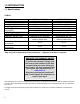
1.0 INTRODUCTION 1.1 Specifications TABLE 1 ITEM INPUT: Hi INPUT: Lo MANIFOLD PRESSURE: Hi MANIFOLD PRESSURE: Lo GAS INLET SUPPLY PRESSURE: ORIFICE SIZE: @ 0-4500’ AIR SHUTTER OPENING CONTROL VALVE TYPE: VENTING Combustion efficiency (fan off) on maximum Combustion efficiency (fan on) on maximum FAN NATURAL GAS (NG) 32,500 Btu/hr (9.5 kW) 22,500 Btu/hr (6.6 kW) 3.5” w.c. (0.82kPa) 1.7” w.c. (0.42kPa) Minimum: 5.0” w.c. (1.25 kPa) Maximum: 10.5” w.c. (1.74 kPa) 2 x #57 DMS (2 x 0.
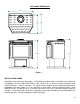
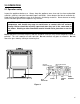
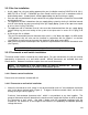
APPLIANCE DIMENSIONS 26 1/16" 5" 1916 11" 2016 29 1/16" 30 1/2" Figure 1 INSTALLATION CODES Installation must conform to local codes. In the absence of local codes, installation must conform to the National Fuel Gas Code, ANSI Z233.1 1988, (in the U.S.), or with the current installation code CAN/CGA B149.1 – M86 (in Canada). The heater, when installed, must be electrically grounded in accordance with local codes or, in the absence of local codes, with the National Electric Code ANSI/NFPA No.
1.2 Features Ignition system: Standing pilot ignition system with thermopile and thermocouple flame detection and piezo igniter. Gas control: Gas control valve type: Automatic millivolt powered combination gas control valve with variable flame control for convenience and on/off switch. The gas valve does not require electricity from an external source.
2.0 OPERATION 2.1 Operation safety Inspect the appliance before use. Always keep the appliance area clear and free from combustible materials, gasoline, and other flammable vapors and liquids. Never obstruct the flow of ventilation air. Keep the front of the appliance clear of all obstacles and foreign materials. Never obstruct or modify the air inlet/outlet grilles of the fireplace in any manner.
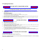
2.2 Lighting instructions FOR YOUR SAFETY, READ BEFORE LIGHTING WARNING: If you do not follow these instructions exactly, a fire or explosion may result causing property damage, personal injury or loss of life. A. B. C. D. This appliance has a pilot which must be lighted by hand. When lighting the pilot, follow these instructions exactly. BEFORE LIGHTING smell all around the appliance area for gas. Be sure to smell next to the floor because some gas is heavier than air and will settle on the floor.
2.3 Heat output adjustment The valve supplied with the appliance has a HI/LO knob to control the heat output and flame height (see Figure 2). 2.4 Fan operation The fan control knob is located on the control panel and may be adjusted to the following settings: OFF: Turn the control fully counter-clockwise until the switch operates. Variable Speed Setting: Turn the control to the desired setting. When the knob is turned fully clockwise the fan will set to minimum speed.
3.0 INSTALLATION 3.1 Installation and safety notes Read all instructions before starting installation and follow them carefully during installation to ensure maximum benefit and safety. Failure to follow these instructions will void your warranty and may present a fire hazard. See the warranty at the back of this manual for disclaimers regarding improper installation. This free standing fireplace and its components are tested and safe when installed in accordance with this installation manual.
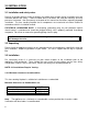
3.3.2 Gas line installation Install supply line using any piping approved for your installation meeting CAN/CGA 6.10, AA 3, ANSI Z21.24 or Z21.45. A qualified gas fitter should install the gas line in accordance with all local building codes. If codes permit, coiled copper tubing may be used for gas supply. Pressure taps are provided on the gas control for test gauge connections to measure the manifold and inlet pressures.
TABLE 2: THERMOSTAT WIRE INFORMATION WIRE SIZE MAX. WIRE LENGTH AWG mm ft. m 22 0.6 10 3.1 20 0.8 25 7.6 18 1.0 40 12.2 16 1.3 64 19.5 14 1.6 100 30.5 2. Solder an appropriate wire connector to each wire. To connect to the burner switch, 1/4" female quick connects are required and to connect directly to the valve use spade tongue connectors. 3. Check tests can be performed on the valve by referring to the trouble shooting guide.
Figure 4 3.3.4 Vent installation 3.3.4.1 Acceptable configurations The stove must be connected to Simpson GS Dura Vent or Security Chimneys International (Secure Vent) 4” x 6 5/8” venting. Install the vent components according to the manufacturer's instructions. Use a maximum of two 90 degree elbows and four 45 degree elbows. Slope horizontal pipe at least 1/4" (6 mm) rise per foot of horizontal run. Allow 2" (50 mm) clearance to the vent.
The minimum vertical length using the maximum horizontal length consists of: • A minimum of 24” (61cm) vertical length directly on top of the stove. • A maximum of one 90 degree elbow. • A maximum of 12” (31cm) total horizontal length. • A wall thimble. • A wall thimble cover. • Horizontal termination cap. For vertical termination: The maximum vertical system consists of: • Up to 30 feet (9m) of vertical length. • Fire stop, flashing, and collar. • High Wind termination cap.
3.3.4.2 Typical vent installation Vent terminals shall not be recessed into a wall or siding.
3.3.4.3 Use of sealant Sealant is required on vent system joints. On longer vent runs, especially vertical runs, sealant will ensure that the combustion air enters from outdoors, and not through the vent joints. Use a sealing product, available from your local Drolet dealer, on the inner pipe joint, applying the sealant around the outside of the male part of the vent. A bead of silicone should be used on the outside of the joint after assembly to seal the supply air.
3.3.4.4 Horizontal wall vent termination The position of the horizontal vent termination must be positioned in such a way as to meet all local building codes. Attach the correct length of vertical section pipe and an elbow fitting to the stove. Mark the center line of the pipe facing the wall (allowing for a 1/4” rise per foot of horizontal, example 10 ft of horizontal would require a rise of 2.5”).
HOT Basement Installations To achieve the minimum vertical rise a 36” snorkel must be used. Where the bottom of the terminal may be blocked by snow, ensure provision is made for adequate drainage. 3.3.4.5 Vertical installation Always maintain a 1” clearance around the vent pipe (vertical) and 2” clearance horizontal, when passing through ceilings, walls, roofs, enclosures, attic rafter or any combustible surfaces. DO NOT PACK AIR SPACES WITH INSULATION.
Through Roof Framing Maintain 10” opening relative to the pitch of the roof. Use a suitable round or square support through the roof. Ensure adequate heat shield protection is provided. Termination above Roof Consult local codes for minimum vent cap height above the roof . To prevent water seepage; install the flashing with upper portion slid under the roofing material and the lower portion over the roofing material. Note: do not fasten down until the final adjustments to the vent have been made.
3.3.4.
3.3.5 Installation of the logs Note: If the pictures in this section are not clear enough, you may see them in color by downloading this owner’s manual via Drolet’s web site at www.drolet.
3.3.6 Initial firing At the time of the first burn, the appliance may emit an odor, accompanied by smoke. This is perfectly normal. As the metal heats to the critical point (about 375 degrees F), part of the paint components turns to light gray smoke as the dormant silicone resin activates and begins to bond with the metal. After the “burn-off” is complete, there will be no more smoke or odor. Although the smoke/odor is not toxic, it is annoying and it displaces oxygen.
3.3.7 Altitude adjustment All valves have been pre-set and certified for installation at elevations from 0 – 4500 feet (1 – 1372m) above sea level. When installing this heater at higher elevations, it is necessary to decrease the input rating by replacing the existing burner orifice with a smaller size for installations over 4500 feet (1372m). The appliances input should be reduced 4% for each additional 1000 feet (305m) above sea level.
4.0 MAINTENANCE 4.1 Maintenance safety Turn off the gas to the main burner and allow the heater to cool for up to 30 minutes before servicing. Service and repair should be done by a qualified service person. The appliance should be inspected before use and at least annually by a professional service technician. More frequent cleaning may be required due to excessive lint from carpeting, bedding material, etc.
4.4 Burner & pilot cleaning Periodic cleaning is necessary for proper operation. Remove the burner, and check that the burner orifice is clean. Visually inspect the pilot. Brush or blow away any dust, lint, or foreign debris. If the pilot orifice is plugged, disassembly may be required to remove any foreign material from the orifice or tubing. 4.5 Fan installation Caution: Label all wires prior to disconnection when servicing controls. Wiring errors can cause improper and dangerous operation.
5.0 TROUBLE SHOOTING SYMPTOM POSSIBLE CAUSE I. A. No spark at electrode (weak or not heat source for pilot ignition) Pilot will not light after repeated triggering of the piezo ignition button 1. Improper ignition 2. Poor connections at igniter and ignition electrode 3. Broken ceramic cover on ignition electrode 4. Defective piezo igniter B. No gas or low gas pressure 1. Gas line shut off(s) may not be turned on 2. No gas supply (LPG) II.
III. Main burner will not light A. Valve / Switches 1. Valve control off 2. Blockage at the burner (line, orifice, or ports) 3. Defective wall switch or thermostat 4. Defective wiring or connections 5. Excessive length of thermostat wire from valve to wall switch or thermostat 6. Wall switch or thermostat incorrectly wired 7. Defective Valve 8. Thermopile may not be generating sufficient voltage (460 mV) 9. Wall switch, thermostat, or wires are defective IV. Soot deposits on glass V.
6.0 REPLACEMENT PARTS When requesting service or replacement parts, refer to your dealer. The following information’s will be asked for; the model name GTX-I, the type of gas used, serial number and proof of purchase. The damaged parts must be replaced by Drolet genuine parts. You can consult the spare parts list on our website at www.drolet.ca or contact your Drolet dealer.
DROLET LIMITED LIFETIME WARRANTY The warranty of the manufacturer extends only to the original consumer purchaser and is not transferable. This warranty covers brand new products only, which have not been altered, modified nor repaired since shipment from factory. Proof of purchase (dated bill of sale), model name and serial number must be supplied when making any warranty claim to your DROLET dealer. This warranty applies to normal residential use only.