Installation and Operation Manual ENGLISH DROLET DECO II (DB03205 model) US Environmental Protection Agency phase II certified wood stove compliant with 2020 cord wood standard Safety tested according to ULC S627, UL 1482 and UL 737 standards by an accredited laboratory. MOBILE HOME CONTACT LOCAL BUILDING OR FIRE OFFICIALS ABOUT RESTRICTIONS AND INSTALLATION INSPECTION REQUIREMENTS IN LOCAL AREA. READ THIS ENTIRE MANUAL BEFORE INSTALLATION AND USE OF THIS WOOD STOVE.
THANK YOU FOR CHOOSING THIS WOOD STOVE. The following pages provide general advice on wood heating, detailed instructions for safe and effective installation, and guidance on how to get the best performance from this stove. To reduce the risk of fire, follow the installation instructions in this manual.
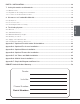
TABLE OF CONTENTS PART A - OPERATION AND MAINTENANCE............................................................................... 7 1. Safety Information.................................................................................................................... 7 2. General Information................................................................................................................. 8 2.1 Performances. . ................................................................................
PART B - INSTALLATION............................................................................................................. 28 7. Safety Information and Standards........................................................................................ 28 7.1 Mobile Home. . ....................................................................................................................28 7.2 Regulations Covering Stove Installation. . ..................................................................
ENGLISH CERTIFICATION PLATE Page 6 Installation and Operation Manual - Drolet Deco II
PART A - OPERATION AND MAINTENANCE 1. Safety Information • WARNING : OPERATE ONLY WITH THE DOOR FULLY CLOSED OR FULLY OPEN WITH THE FIRE SCREEN IN PLACE. IF THE DOOR IS LEFT PARTLY OPEN, GAS AND FLAME MAY BE DRAWN OUT OF THE OPENING, CREATING RISKS FROM BOTH FIRE AND SMOKE. • HOT WHILE IN OPERATION, KEEP CHILDREN, CLOTHING AND FURNITURE AWAY. CONTACT MAY CAUSE SKIN BURNS. GLOVES MAY BE NEEDED FOR THE STOVE OPERATION.
2. General Information 2.1 Performances ENGLISH Values are as measured per test method, except for the recommended heating area, firebox volume, maximum burn time and maximum heat output. Model DROLET DECO II (DB03205) Combustion Technology Non catalytic Fuel Type Dry Cordwood Recommended heating area (sq. ft. .) 1 500 to 1,800 ft 2 (46 to 167 m 2) Firebox volume 1.9 ft 3 (0.054 m 3) EPA loading volume 1.44 ft 3 (0.
Specifications Maximum log length 10 18 in (457 mm) east-west Flue outlet diameter 6 in (150 mm) Recommended connector pipe diameter 6 in (150 mm) Type of chimney ULC S629, UL 103 HT (2100 °F) Baffle material Vermiculite Approved for alcove installation Yes Approved for mobile home installation 11 Yes Type of door Simple, glass with cast iron frame Type of glass Ceramic glass Blower Optional (up to 100 CFM) Particulate emission standard 12 EPA / CSA B415.
2.
2.4 Materials The body of this stove, which is most of its weight, is carbon steel. Should it ever become necessary many years in the future, almost the entire stove can be recycled into new products, thus eliminating the need to mine new materials. The paint coating on the stove is very thin. Its VOC content (Volatile Organic Compounds) is very low.
The success of zone heating will depend on several factors, including the correct sizing and location of the stove, the size, layout and age of the home and the climate zone. Three-season vacation homes can usually be heated with smaller stoves than houses that are heated all winter. 2.
Softer woods make good fuel for mild weather in spring and fall because they light quickly and produce less heat. Softwoods are not as dense as hardwoods so a given volume of wood contains less energy. Using softwoods avoids overheating the house, which can be a common problem with wood heating in moderate weather. Harder woods are best for colder winter weather when more heat and longer burn cycles are desirable.
3.5 Drying Time Firewood that is not dry enough to burn is the cause of most complaints about wood burning appliances. Continually burning green or unseasoned wood produces more creosote and involves lack of heat and dirty glass door. Firewood with a moisture content between 15% and 20% will allow the stove to produce its highest possible efficiency.
4. Operating the Stove This wood heater has a manufacturer-set minimum low burn rate that must not be altered. It is against federal regulations to alter this setting or otherwise operate this wood heater in a manner inconsistent with operating instructions in this manual.
The blower has a variable speed control that can be adjusted in three different positions; either from high (HI) to low (LO) or closed (OFF). ENGLISH Allow the stove to reach operating temperature (approximately one hour) before turning on the blower, since increased airflow from the blower will remove heat and affect the start up combustion efficiency. HI OFF It is possible to add a heat sensor, sold separately, to the blower.
5.2 Lighting Fires Each person heating with wood develops its own favorite way to light fires. Regardless of the method chosen, the goal should be to have a hot fire burning, quickly. A fire that ignites fast produces less smoke and deposits less creosote in the chimney. Never use gasoline, gasoline-type lantern fuel (naphtha), fuel oil, motor oil, kerosene, charcoal lighter fluid, or similar liquids or aerosols to start or ‘freshen up’ a fire in this wood stove.
5.2.4 Using Fire Starters Commercial fire starters can be used instead of a newspaper. Some of these starters are made of sawdust and wax and others are made of specialized flammable solid chemicals. Always follow the package directions when using. Gel starters can also be used, but only to light a fire, in a cold combustion chamber without hot embers inside. ENGLISH 5.3 Combustion Cycles Wood heating with a space heater is very different than other forms of heating.
smothered by the new load of wood. When the embers are simply spread inside the combustion chamber, the new load smoulder for a long time before igniting. Close the air control only when the firebox is full of bright turbulent flames, the wood is charred, and its edges are glowing. When lighting a new load, the appliance produces a heat surge. This heat surge is pleasant when the room temperature is cool but can be unpleasant when the room is already warm.
On the other hand, too much air can make the fire uncontrollable, creating very high temperatures in the unit as well as in the chimney and seriously damaging them. A reddish glow on the unit and on the chimney components indicates overheating. Excessive temperatures can cause a chimney fire. 5.7 Fire Types ENGLISH Using the air intake control is not the only way to match the appliance heat output to the desired temperature in the house.
The table below gives an approximate maximum burn cycle time, based on firebox volume. FIREBOX VOLUME MAXIMUM BURN CYCLE TIME <1.5 cubic feet 3 to 5 hours 1.5 c.f. to 2.0 c.f 5 to 6 hours 2.0 c.f. to 2.5 c.f. 6 to 8 hours 2.5 c.f. to 3.0 c.f. 8 to 9 hours >3.0 c.f. 9 to 10 hours A longer burning time is not necessarily an indication of efficient operation.
6. Maintenance This heater will give many years of reliable service if used and maintained properly. Internal components of the firebox such as firebricks or refractory panels, baffle and air tubes will wear over time. Defective parts should always be replaced with original parts. To avoid premature deterioration, follow the lighting and reloading procedures in section «5. Burning Wood Efficiently» and also avoid letting the heater run with the air intake fully open for entire burn cycles. ENGLISH 6.
When the stove runs at a low combustion rate, light brown stains may form, especially in the lower corners of the glass. This indicates that the fire has been smoky and some of the smoke has condensed on the glass. It also indicates incomplete combustion of the wood, which also means more smoke emissions and faster formation of creosote in the chimney. The deposits that form on the glass are the best indication of the fuel quality and success in properly using the stove.
6.3.3 Gasket ENGLISH The glass gasket is flat, adhesive-backed, woven fibreglass. The gasket must be centred on the edge of the glass. 1. Follow the steps of the previous section to remove the glass. 2. Remove the old gasket and clean the glass thoroughly. 3. Peel back a section of the paper covering the adhesive and place the gasket on a table with the adhesive side up. 4.
6.4.2 Gasket 1. Remove the door and place it face-down on something soft like a cushion of rags or a piece of carpet. 2. Remove the old gasket from the door. Use a screwdriver to scrape the old gasket adhesive from the door gasket groove. 3. Apply a bead of approximately 3/16" (5 mm) of high temperature silicone in the door gasket groove. Starting from the middle, hinges side, press the gasket into the groove. The gasket must not be stretched during installation. 4.
positions désirées. Les configurations 1-2-3-4-5-6, indiquent dans quel direction celles-ci agissent sur l’ajustement de la porte 4 ENGLISH A 2 1 B 3 6.5 5 6 Exhaust System Wood smoke can condense inside the chimney, forming a inflammable deposit called creosote. If creosote builds up in the system, it can ignite when a hot fire is burned in the stove. A very hot fire can progress to the top of the chimney. Severe chimney fires can damage even the best chimney.
Establish a routine for the fuel, wood burner and firing technique. Check daily for creosote build-up until experience shows how often you need to clean to be safe. Be aware that the hotter the fire the less creosote is deposited, and weekly cleaning may be necessary in mild weather even though monthly cleaning may be enough in the coldest months. Contact your local municipal or provincial fire authority for information on how to handle a chimney fire.
PART B - INSTALLATION 7. Safety Information and Standards • The information given on the certification label affixed to the appliance always overrides the information published, in any other media (owner’s manual, catalogues, flyers, magazines and web sites). ENGLISH • Mixing of appliance components from different sources or modifying components may result in hazardous conditions. Where any such changes are planned, Stove Builder International Inc. Should be contacted in advance.
7.3 Location of the Certification Label Since the information given on the certification label affixed to the appliance always overrides the information published, in any other media (owner’s manual, catalogues, flyers, magazines and web sites) it is important to refer to it in order to have a safe and compliant installation. In addition, important information about the stove can be found (model, serial number, etc.). The certification label is located on the back of the stove. 8.
A F D B F E ENGLISH C CAN US 48" 36" 122 cm 92 cm Clearances - Top Clearances - Corner Ve Ho 84" (L) 213 cm N Clearances - Side Page 30 Installation and Operation Manual - Drolet Deco II
Clearances APPLIANCE CLEARANCES WITH SINGLE WALL PIPE CONNECTOR Canada USA A 14 ½" (368 mm) 13" (330 mm) B 16" (406 mm) C 12" (305 mm) APPLIANCE CLEARANCES WITH DOUBLE WALL PIPE CONNECTOR Canada USA A 7 ½" (191 mm) 7 ½" (191 mm) 15" (381 mm) B 16" (406 mm) 15" (381 mm) 12" (305 mm) C 12" (305 mm) 12" (305 mm) If the above clearances are met, then the distances measured from the flue outlet will be: DISTANCES 13 FROM PIPE CONNECTOR WITH SINGLE WALL PIPE CONNECTOR Canada USA D 18" (4
8.1.
Inside an Alcove APPLIANCE CLEARANCES WITH DOUBLE WALL PIPE CONNECTOR Canada USA A 8" (203 mm) 8" (203 mm) B 19" (483 mm) 19" (483 mm) K 48" (1219 mm) 48" (1219 mm) L 78" (1981 mm) 78" (1981 mm) 8.1.5 DISTANCES 17 FROM PIPE CONNECTOR WITH DOUBLE WALL PIPE CONNECTOR Canada USA D 11 ½" (292 mm) 11 ½" (292 mm) E 28" (711 mm) 28" (711 mm) ENGLISH 8.1.4 Mobile Home It is strictly forbidden to install a unit with a single wall pipe in a mobile home.
8.2 Floor Protection This stove is designed to prevent the floor from overheating. However, it must be placed on a nonflammable surface to protect the floor from hot embers that may fall during loading. The floor protection must be a continuous, non combustible material, such as steel with a minimum thickness of 0.015" (0.38 mm) or ceramic tiles sealed together with grout. Cement board, brick, or any other approved or listed material suited for floor protection. No R factor required.
CLEARANCES MAY BE REDUCED BY THESE PERCENTAGES SIDES AND REAR CAN / USA (%) Sheet metal, a minimum of 24 gauge (0.61 mm) in thickness , spaced out at least 1" (25 mm)* by non-combustible spacers 67 Ceramic tiles, or equivalent non-combustible material, on non-combustible board spaced out at least 1" (25 mm)* by non-combustible spacers Ceramic tiles, or equivalent non-combustible material, on non-combustible board, with a minimum of 24 gauge (0.
8.3.2 Shield Construction Rules − Adhesives used in shield construction must not ignite or lose its adhesive qualities at temperatures likely to be encountered. − Mounting hardware which extends from the shield surface into combustibles may be used only at the edges of the shield. − Mounting hardware must allow full vertical ventilation. ENGLISH See figures on next page for shield construction to match each letter to a clearance.
ENGLISH Heat shield clearances Heat shield clearances Heat shield clearances Installation and Operation Manual - Drolet Deco II Page 37
9. The Venting System 9.1 General The venting system, made of the chimney and the connecting pipe between the stove and the chimney, acts as the engine that drives the wood heating system. Even the best stove will not function safely and efficiently if it is not connected to a suitable chimney. ENGLISH The heat in the flue gases that pass from the stove and chimney connector into the chimney is not waste heat.
9.2.2 Factory-Built Metal Chimneys in Mobile Homes For use in a mobile home, this stove is to be connected to a 6" double wall factory built chimney pipe conforming to ULC-S629 or UL 103HT standards for 650°C Factory-built chimney. The total length of the flue system should be at least 12 feet including elbows, from the top of the stove. 9.2.
9.3 Minimum Chimney Height ENGLISH The top of the chimney should be tall enough to be above the air turbulence caused when wind blows against the house and its roof. The chimney must extend at least 3 ft. (1 m) above the highest point of contact with the roof, and at least 2 ft. (60 cm) higher than any roof line or obstacle within a horizontal distance of 10 ft. (3 m). 9.
If there is no fire burning in a heater connected to a chimney that is shorter than the warm space inside the house, the slight negative pressure in the lower part of the house will compete against the desired upward flow in the chimney. This occurs for the two following reasons: First, the chimney runs up the outside of the house, so the air in it is colder and denser than the warm air in the house.
If an air intake is installed through the wall of the house, its pressure can vary during windy weather. If there are changes in wood stove performance in windy weather, and in particular if smoke puffs from the stove, the air duct should be disconnected from the stove to determine if it is the cause of the problem. In some windy conditions, negative pressure at the duct weather hood outside the house wall may draw hot exhaust gases from the stove backwards through the duct to outdoors.
The rules below are based on those found in the CSA B365 installation code. Please carefully follow these installation instruction rules, or those enforced by the local code. • Maximum overall length of horizontal pipe: 10 ft. (3 m) including elbows. • Minimum clearance from combustible material: 18" (450 mm). The minimum clearance may be reduced by 50 percent to 9" (225 mm) if suitable shielding is installed either on the pipe or on the combustible surface.
Appendix 1: OPTIONAL FRESH AIR INTAKE KIT INSTALLATION ENGLISH The configutation of this appliance do not allow the air intake to be installed underneath the pedestal. It can only be installed on the back. This mobile home approved stove requires the installation of a fresh air intake kit (A) and an insulated fresh air intake pipe (HVAC type, must meet ULC S110 or UL 181 class 0 or class 1) (B), sold separately. Refer to air intake kit installation instructions for more details.
Appendix 2: OPTIONAL FIRE SCREEN INSTALLATION This product should not be operated with door open using fire screen (AC01299) in states or provinces where particulate matter emission rate limit is enforced (ex: EPA). Open the door. 2. Hold the fire screen by the two handles and bring it close to the door opening. 3. Lean the upper part of the fire screen against the top door opening making sure to stove the top fire screen brackets behind the primary air deflector. ENGLISH 1. 4.
Appendix 3: OPTIONAL BLOWER INSTALLATION A blower, sold separately, can be installed on the stove. 1. Remove the backplate by cutting the knockouts with pliers. ENGLISH MICROJOINTS 2. Screw the blower (A) in place using the screws (B) included in the installation manual. Ensure that the blower’s power cord is not in contact with any surface of the stove to prevent electrical shock or fire damage. Do not run the power cord beneath the stove.
Appendix 4: OPTIONAL THERMODISC INSTALLATION A thermodisc, sold separately, can be installed with the blower. It allows the fan to operate only when the stove is hot enough. See the instructions provided with the thermodisc for more details. Screw the thermodisc (A) with the screws (B) provided on the back of the stove. ENGLISH The electrical cord of the thermodisc should not touch any surface of the stove to avoid electric shock or fire. Do not run the power cord under the stove.
Appendix 5: AIR TUBES AND BAFFLE INSTALLATION Starting with the rear tube, lean and insert the right end of the secondary air tube into the rear right channel hole. Then lift and insert the left end of the tube into the rear left channel. 2. Align the notch in the left end of the tube with the key of the left air channel hole. Using a « Wise grip » hold the tube and lock it in place by turning the tube as shown. Make sure the notch reaches the end of the key way. 3. Put the baffle in place. 4.
ENGLISH Note that secondary air tubes (B) can be replaced without removing the baffle board (A) and that all tubes are identical.
ENGLISH Appendix 6: MOBILE HOME INSTALLATION 2x Page 50 Installation and Operation Manual - Drolet Deco II
Appendix 7: EXPLODED DIAGRAM AND PARTS LIST ï î í ì ê ïð é ENGLISH ë ïð ïï ïð ïð ïð ïð ïï ïð è ïð ïî ïï ç ïð ïí ïð ïï ïð ïð ïì é ïé ïë ïè ïê ïç îì îë ïè ïè îí îð îî íî îê îé íì îï îç ïè îè ìï íð íé íï íè íí íë íç íê ïð ìî ìí Installation and Operation Manual - Drolet Deco II Page 51
ENGLISH IMPORTANT: THIS IS DATED INFORMATION. When requesting service or replacement parts for your unit, please provide the model number and the serial number. We reserve the right to change parts due to technology upgrades or availability. Contact an authorized dealer to obtain any of these parts. Never use substitute materials. Use of non-approved parts can result in poor performance and safety hazards.
Item Description Qty 36 AC06500 SILICONE AND 5/8" X 8' BLACK DOOR GASKET KIT 1 37 PL70968 DOOR HANDLE 1 38 30742 DRILLED BLACK WOODEN DOOR HANDLE 1 39 30185 17/64" AA TYPE WASHER BLACK 1 40 30025 1/4-20 X 1/2" PAN-HEAD QUADREX BLACK SCREW 1 41 AC01299 RIGID FIRESCREEN 1 42 30898 ROUND WOODEN BLACK HANDLE DULL BLACK FINISH 1 43 SE70906 ASH DRAWER ASSEMBLY 1 ENGLISH # Installation and Operation Manual - Drolet Deco II Page 53
DROLET LIMITED LIFETIME WARRANTY DROLET LIMITED LIFETIME WARRANTY The warranty of the manufacturer extends only to the original retail purchaser and is not transferable. This warranty covers brand new products only, which have not been altered, modified nor repaired since shipment from the factory. Proof of purchase (dated bill of sale), model name and serial number must be supplied when making any warranty claim to the DROLET dealer. This warranty applies to normal residential use only.
This document is available for free download on the Stove Builder International inc. manufacturer’s website. It is a copyrighted document. 250, rue de Copenhague, Resale is strictly prohibited. The manufacturer may update St-Augustin-de-Desmaures (Québec) Canada this document from time to time and cannot be responsible G3A 2H3 for problems, injuries, or damages arising out of the use 418-908-8002 of information contained in any document obtained from https://www.drolet.