
Data Sheet

© MSW Motion Control GmbH Vertriebsgesellschaft Page 4 of 4
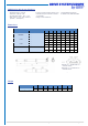
Front and rear connector
Front connector (piston rod)
Rear connector (gear cover)
1 2 = Standard
1 = Standard 2
CAUTION:
C21 is standard and will not be specified in the type code.
If at least one connector is changed, option C must be attached to the type code (e.g., DSZY35…-IP69K-C11)
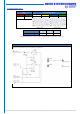
Mounting material
Mounting bracket DSZY4-H02
Caution with rear attachment:
Due to the cable routeing, the actuator is
here only swivelling to a limited extent.
Installation instructions
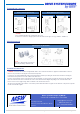
CAUTION: The DSZY35 does not have integrated limit switches. This electric linear actuator is supplied as standard with a 2-channel
Hall sensor to prevent it from moving into its mechanical end positions.
In general, we recommend additionally setting separate limit switches and thus preventing the electric linear actuator from moving into
its mechanical end positions in the event of failure of the hall sensors.
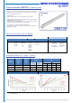
It must be ensured that the load is not greater than shown in the diagram. To protect against overload, the voltage must be switched off
when the maximum rated current is reached. This can be read in the load-current diagram depending on the selected reduction ratio.
Please note the correct supply voltage, which is indicated on the electric linear actuator.
The piston rod extends when the red wire is connected to positive and the black wire to negative. For the retraction of the piston rod, positive
must be reversed with negative.
Drive System Europe by MSW
®
A trade mark of MSW Motion Control GmbH
MSW Motion Control GmbH
Vertriebsgesellschaft
Schloßstr. 32/34, 33824 Werther (Westf.)
Germany
anfrage@msw-motion.de
www.msw-motion.de
Tel.: +49 (0)5203 919200
Errors and technical changes excepted.
Version: 15 January 2022