
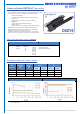
Data Sheet

© MSW Motion Control GmbH Vertriebsgesellschaft Page 4 of 4
Installation instructions
It must be ensured that the load is not greater than shown in the diagram. To protect against overload, the voltage must be switched
off when the maximum rated current is reached. This can be read in the load-current diagram depending on the selected reduction
ratio. Please note the correct supply voltage, which is indicated on the electric linear actuator.
The piston rod is secured against twisting.
The load must always be centered in the direction of movement. Transverse forces must be avoided. They shorten the service life and
can impede the function or lead to irreparable damage in extreme cases.
The actuator has a mechanical overload clutch. The activation of this clutch is expressed in a loud rattling sound.
CAUTION: The overload clutch is not designed for permanent use. Rather, it is intended for emergencies if, for example, the power
monitoring fails. For the standard version of the actuator the use of external limit switches is therefore strongly recommended.
CAUTION: Please note the correct wiring for retraction or extension. The connection diagram can be found at the top of the
specification sheet.
The integrated limit switches can be set by the customer. You can find instructions about this on our homepage. The maximum stroke
is always set in the delivery state
Drive System Europe by MSW
®
A trade mark of MSW Motion Control GmbH
MSW Motion Control GmbH
Vertriebsgesellschaft
Schloßstr. 32/34, 33824 Werther (Westf.)
Germany
anfrage@msw-motion.de
www.msw-motion.de
Tel.: +49 (0)5203 919200
Errors and technical changes excepted.
Version: 15 January 2022