READ AND SAVE THESE INSTRUCTIONS VAPORMIST ® Electric-to-Steam Humidifier Installation, Operation, and Maintenance Manual
WARNINGS AND CAUTIONS Warnings and cautions WARNING Indicates a hazardous situation that could result in death or serious injury if instructions are not followed. CAUTION Indicates a hazardous situation that could result in damage to or destruction of property if instructions are not followed. mc_051508_1145 WARNING Attention installer Read this manual before installing, and leave this manual with product owner.
Warnings and cautions WARNING Disconnect electrical power Disconnect electrical power before installing supply wiring or performing service or maintenance procedures on any part of the humidification system. Failure to disconnect electrical power could result in fire, electrical shock, and other hazardous conditions. These hazardous conditions could cause property damage, personal injury, or death.
Table of contents ATTENTION INSTALLER Read this manual before installing. Leave manual with product owner. DriSteem® Technical Support 800-328-4447 WHERE TO FIND MORE INFORMATION Our web site: The following documents are available on our web site: www.dristeem.
Table of contents Keypad/display and troubleshooting OPERATION Principle of operation. . . . . . . . . . . . . . . . . . . . . . . . . . . . . . . . . . . . . 37 Start-up checklist . . . . . . . . . . . . . . . . . . . . . . . . . . . . . . . . . . . . . . . . 38 Start-up procedure . . . . . . . . . . . . . . . . . . . . . . . . . . . . . . . . . . . . . . . 39 MAINTENANCE Tap/softened water . . . . . . . . . . . . . . . . . . . . . . . . . . . . . . . . . . . . . . 40 RO/DI water option . . . . . . . .
OVERVIEW Product overview Vapormist humidifiers use heat caused by electrical resistance in submerged heating elements boil fill water into humidification steam. Water level is controlled by means of conductivity probes or a float valve, depending on the water type. Supply water quality is an important component of humidifier reliability and maintenance. Examples: • Corrosive water can decrease the service life of the humidifier.
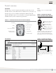
OVERVIEW Product overview CONTROLLER Notes: The Vapor-logic controller in Vapormist humidifiers provides menus for all humidifier functions, with a Web interface for Ethernet access (see Figure 3-1). See Pages 10 and 11 for detailed installation drawings. The Vapor-logic version 5 Installation and Operation Manual ships with Vapormist humidifiers. Refer to it for information on using the keypad/display and Web interface, and for troubleshooting information.
SPECIFICATIONS Capacities, electrical specifications, and weights Table 4-1: Vapormist capacities, electrical specifications, and weights VM model Current draw (amps) Maximum steam capacity kW lbs/hr kg/h 2 6 Weights ‡ Single-phase Three-phase Shipping Operating 120V 208V* 240V* 277V 480V† 600V† 208V* 240V† 277V 480V† 600V† lbs kg lbs kg 2.7 16.7 80 36 95 43 9.6 8.3 7.2 4.2 3.3 — — 7.2** 5.8** 80 36 95 43 10.0 25.0** 21.7** 18.8 10.8** 8.
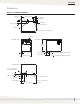
SPECIFICATIONS Dimensions FIGURE 5-1: VAPORMIST DIMENSIONS Top view 24.2" (614 mm) 2" (50 mm) 10.9" (276 mm) 2" (50 mm) 1" (25 mm) Power wiring knockout 2.25" (57 mm) Steam outlet Control or SDU wiring knockout Venting Left side view Front view 18.6" (472 mm) 2.25" (57 mm) 1.50" (38 mm) 5.75" (146 mm) 16.1" (409 mm) 3/4" pipe thread (DN20) frame drain 3/4" pipe thread (DN20) tank drain Bottom view 0.50" (13 mm) hole in base for water fill line DC-1167 0.75" (19 mm) 0.63" (16 mm) 2.
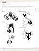
SPECIFICATIONS Dispersion options The duct dispersion options in Figure 6-1 and the open space dispersion options in Figure 6-2 are available for Vapormist humidifiers. For installation details, see “Dispersion” beginning on Page 18.
SPECIFICATIONS Selecting a location HUMIDIFIER FIGURE 7-1: INSTALLATION OVERVIEW When selecting a location for the humidifier, consider the following: • Proximity to the duct Install the humidifier near the air duct system where the dispersion assembly will be located. The maximum recommended length for steam hose connecting a single humidifier to a dispersion assembly is 10' (3 m). The maximum recommended developed length for tubing connecting a single humidifier to a dispersion assembly is 20' (6 m).
INSTALLATION Mounting WALL MOUNTING THE HUMIDIFIER Mount the humidifier level and plumb, using the lag bolts provided. Follow the instructions below for mounting on a stud wall with wood studs 16" (406 mm) on center. See Figures 10-1 and 11-1. 1. Mark hole locations at centers of studs, and predrill 1/4" (6 mm) diameter pilot holes. 2. Secure cabinet to wall with lag bolts provided. See mounting keyholes in Figure 8-1. Note: Use the appropriate mounting methods and mounting hardware for other wall types.
INSTALLATION Mounting FIGURE 9-1: VAPORMIST CLEARANCE RECOMMENDATIONS Maintain these clearances for service and maintenance.
INSTALLATION Piping: Tap/softened water FIGURE 10-1: VAPORMIST (TAP/SOFTENED WATER) FIELD PIPING OVERVIEW Steam hose (maximum run 10' [3 m]). May also use tubing. See the DriSteem Design Guide for maximum tubing lengths. Water supply line: • 1/4" NPT (DN8) connection size • 25 to 80 psi (175 to 550 kPa) required water pressure. • If water piping to humidifier is nonmetallic, the first 3' (1 m) of water supply piping from humidifier should be metallic.
INSTALLATION Piping: RO/DI water option FIGURE 11-1: VAPORMIST (RO/DI WATER OPTION) FIELD PIPING OVERVIEW Steam hose (maximum run 10' [3 m]). May also use tubing. See the DriSteem Design Guide for maximum tubing lengths. Water supply line: • ¼" NPT (DN8) connection size • 25 to 80 psi (175 to 550 kPa) required water pressure.
INSTALLATION Piping: Supply water and drain piping Supply water piping may be of any code-approved material (copper, steel, or plastic). The fill valve connection size is a 1/4" pipe thread (DN8) fitting except in Europe where it is a DN10 pipe thread fitting. In cases where water hammer may be a possibility, consider installing a shock arrestor. Water pressure must be between 25 psi and 80 psi (175 kPa and 550 kPa).
INSTALLATION Piping: Drane-kooler FIGURE 13-1: DRANE-KOOLER FIELD PIPING CONNECTIONS Notes: • Dashed lines indicate provided by installer. • Total length of pipe between humidifier and Drane-kooler not to exceed 10' (3 m). Tank drain Field piping Frame drain Hot drain water inlet, 1" (DN25) Vacuum breaker Union Supply water shut-off valve Union Union Suppy water inlet, 3/8" (DN10) 25 to 80 psi (172 to 552 kPa) Maximum temperature 70 °F (21 °C) Tempered water overflow 12 gpm (45.
INSTALLATION Wiring HUMIDIFIER FIELD WIRING All wiring must be in accordance with all governing codes, and with the humidifier wiring diagrams. The diagrams are located inside the removable subpanel cover on the right side of the humidifier cabinet. Power supply wiring must be rated for 220 °F (105 °C). When selecting a location for installing the humidifier, avoid areas close to sources of electromagnetic emissions such as power distribution transformers.
INSTALLATION Wiring FIGURE 15-1: SHIELDED/SCREENED CABLE DRAIN WIRE CONNECTION TO LUG Humidifier side view Vapor-logic keypad/display Microprocessor board OM-1505 Shield/screen ground lug Note: For maximum EMC effectiveness, all humidity, temperature, and airflow controls should be wired using multicolored shielded/screened plenum-rated cable with a drain wire for the shield/screen. The drain wire should be connected to the shield/screen ground terminal with its length kept to less than 2" (50 mm).
INSTALLATION Sensor placement SENSOR LOCATION IS CRITICAL Other factors affecting humidity control Sensor location has a significant impact on humidifier performance. See the recommendations below and Figure 17-1. Humidity control involves more than the controller’s ability to control the system. Other factors that play an important role in overall system control are: Note: DriSteem recommends that you do not interchange room and duct humidity devices.
INSTALLATION Sensor placement FIGURE 17-1: RECOMMENDED SENSOR LOCATIONS 8' to 12' (2.4 m to 3.7 m) min.
INSTALLATION Dispersion: Selecting the dispersion assembly location DriSteem humidifiers operate with several types of dispersion assemblies for open spaces and for ducts and air handling units. FIGURE 18-1: ULTRA-SORB WITH THE HIGH-EFFICIENCY TUBE OPTION Dispersion assemblies in ducts and air handling units must be positioned where the water vapor being discharged is carried off with the airstream and is absorbed before it can cause condensation or dripping.
INSTALLATION Dispersion: Interconnecting piping requirements Important: The steam outlet on the humidifier is sized to the output of the humidifier. DO NOT use steam hose or tubing with an inside diameter smaller than the humidifier steam outlet. See note at left. Reducing the inside diameter of the steam hose or tubing will result in the internal humidifier system pressure exceeding the parameters for acceptable performance. • See maximum steam carrying capacities in Table 19-1.
INSTALLATION Dispersion: Interconnecting piping requirements CONNECTING TO HUMIDIFIER WITH TUBING • See Figures 28-1 and 29-1 for interconnecting tubing pitch requirements for single dispersion tube applications. See Table 31-1 for interconnecting tubing pitch requirements for Rapid-sorb applications. WARNING Excessive moisture hazard DriSteem strongly recommends installing a duct airflow proving switch and a duct high limit humidistat.
INSTALLATION Dispersion: Drip tee installation Install a drip tee as shown below when the humidifier is mounted higher than the dispersion assembly, when interconnecting hose or tubing needs to go over an obstruction, or when interconnecting piping runs are long. Important: Steam hose must be supported to prevent sagging or low spots. WARNING Hot surface and steam hazard Dispersion tube, steam hose, or tubingcan contain steam, and surfaces can be hot. Discharged steam is not visible.
INSTALLATION Dispersion: SDU-I and SDU-E SDU-I is available for Vapormist humidifier models VM-2 through VM-10. SDU-I: Instant, internal absorption SDU-E is available for all Vapormist humidifiers except VM-2 and models using 240V, 277V, and 480V three-phase power with the SSR control option and drawing more than 32.7 amps. SDU-I (Space Distribution Unit Internal Absorption) disperses humidity with no visible vapor trail or wetness, making it ideal for use in finished spaces.
INSTALLATION Dispersion: SDU-I and SDU-E FIGURE 23-1: WALL-MOUNTED VAPORMIST AND SDU-I Keyhole for 3/8" dia. (M10) fasteners 16" (406 mm) SDU chassis 3" (76 mm) 17.75" (451 mm) 18.02" (458 mm) 16" (406 mm) 0.25" (6.4 mm) 3" (76 mm) Keyhole for 3/8" dia. (M10) fasteners 18.50" (470 mm) Vapormist chassis 24" (610 mm) OM-282-4 mc_052610_1505-VM FIGURE 23-2: WALL-MOUNTED VAPORMIST AND SDU-E Keyhole for 3/8" dia. (M10) fasteners 16" (406 mm) SDU chassis 3" (76 mm) 18.
INSTALLATION Dispersion: SDU-I and SDU-E Table 24-1: SDU specifications Maximum capacity Shipping weight Amps at 120V Horsepower (50/60 Hz) SDU model lbs/hr kg/h lbs kg SDU-I 30 13.6 68 31 3.20 SDU-E 102 46.3 61 28 2.07 cfm m3/s dB* 1/5 760 0.36 58 1/8 545 0.26 64 * Measurement taken 6.5' (2 m) in front of SDU cabinet. mc_042710_1440-NA FIGURE 24-1: SDU-I MECHANICAL DETAIL Front view 24.2" (615 mm) Side view Humidified air discharge grille 16.1" (409 mm) 18.
INSTALLATION Dispersion: SDU-I and SDU-E SDU-E CONDENSATE DRAIN CONNECTION Mounting SDU-E 1. Piping must be minimum 3/4" I.D. (DN20) and rated for 212 °F (100 °C) minimum continuous operating temperature. • SDU-E requires an installed condensate drain line and water seal (provided by installer). See Figure 25-1 and instructions at left. 2. Drain line must be piped as shown in Figure 25-1.
INSTALLATION Dispersion: SDU-I and SDU-E SDU-E RISE, SPREAD, AND THROW As steam is discharged from the SDU-E, it quickly cools and turns to a visible fog that is lighter than air. As this fog is carried away from the SDU-E by the airstream, it tends to rise toward the ceiling. If this fog contacts solid surfaces (columns, beams, ceiling, pipes, etc.) before it disappears, it could collect and drip as water. The greater the space relative humidity, the more the fog will rise, throw and spread.
INSTALLATION Dispersion: SDU-I and SDU-E Table 27-1: SDU-E minimum nonwetting distances kW 40% RH @ 70 °F (21 °C) Maximum steam capacity Rise Spread 50% RH @ 70 °F (21 °C) Throw Rise Spread 60% RH @ 70 °F (21 °C) Throw Rise Spread Throw lbs/hr kg/h ft m ft m ft m ft m ft m ft m ft m ft m ft m 2 6 2.7 1.0 0.3 1.0 0.3 5.0 1.5 1.5 0.5 1.5 0.5 6.5 2.0 2.5 0.8 2.5 0.8 7.5 2.3 4 12 5.4 1.0 0.3 1.0 0.3 5.0 1.5 1.5 0.5 1.5 0.5 6.5 2.0 2.5 0.
INSTALLATION Dispersion: Single dispersion tube FIGURE 28-1: SINGLE DISPERSION TUBE WITHOUT CONDENSATE DRAIN Duct Single dispersion tube without condensate drain Steam hose or tubing. Insulate tubing to reduce steam loss. Do not insulate steam hose. See Table 19-1 for maximum piping lengths. Mounting nut 3/8" - 16 (M10) Pitch* See the first bullet in Installation notes.
INSTALLATION Dispersion: Single dispersion tube FIGURE 29-1: SINGLE DISPERSION TUBE WITH CONDENSATE DRAIN Single dispersion tube with condensate drain Duct Secure and seal escutcheon plates Steam hose or tubing. Insulate tubing to reduce steam loss. Do not insulate steam hose. See Table 19-1 for maximum piping lengths. Mounting nut 3/8" - 16 (M10) Pitch* 90° long sweep or two 45° elbows Pitch tube toward drain 1/8"/ft (1%) 6" (150 mm) recommended See the first bullet in Installation notes.
INSTALLATION Dispersion: Rapid-sorb Read all dispersion instructions in this manual, and follow the installation instructions below: • Unpack shipment and verify receipt of all Rapid-sorb components with packing list. Report any shortages to DriSteem immediately. The components typically include the following: – Multiple dispersion tubes – Header – 3/4" × 2" (19 mm × 51 mm) L-bracket WARNING Hot surface and steam hazard Dispersion tube, steam hose, or tubing can contain steam, and surfaces can be hot.
INSTALLATION Dispersion: Rapid-sorb Pitch requirements • For Rapid-sorb with the header outside a horizontal-airflow duct, consider the following: – 1½" (DN40) dispersion tubes: Use a fastener of sufficient length to accommodate the 1/8"/ft (1%) pitch requirements toward the 3/4" pipe thread (DN20) header drain fitting. – 2" (DN50) dispersion tubes: The bracket can be mounted flush to the ductwork.
INSTALLATION Dispersion: Rapid-sorb FIGURE 32-1: RAPID-SORB IN A HORIZONTAL AIRFLOW WITH HEADER OUTSIDE THE DUCT Position L-bracket so that flange is upstream of dispersion tubes. Drawing shows L-bracket positioned for airflow back to front. Dashed lines indicate provided by installer. L-bracket Air Dispersion tube flow Duct Point tubelets perpendicular to airflow 90° long sweep or two 45° elbows Steam hose or tubing. Insulate tubing to reduce steam loss. Do not insulate steam hose.
INSTALLATION Dispersion: Rapid-sorb 4. Position the flange of the L-bracket so it is upstream of the tubes when the assembly is raised and fastened into position. Fasten the L-bracket to the end of the dispersion tubes with the provided bolt, lock washer, and flat washer. Note: See Page 36 for steam supply and condensate drain line connection instructions. 5. Before tightening the L-bracket bolts to the dispersion tubes: • For 1½" (DN40) dispersion tubes: – Dispersion tube will rotate in slip coupling.
INSTALLATION Dispersion: Rapid-sorb FIGURE 34-1: RAPID-SORB IN A HORIZONTAL AIRFLOW WITH HEADER INSIDE THE DUCT Position L-bracket so that flange is upstream of dispersion tubes. This drawing shows the L-bracket positioned for airflow back to front Dispersion tube Air Point tubelets (steam orifices) perpendicular to airflow w flo Duct Slip coupling or hose cuff 90° long sweep or two 45° elbows Support bracket Pitch* Steam hose or tubing. Insulate tubing to reduce steam loss. Do not insulate steam hose.
INSTALLATION Dispersion: Rapid-sorb 5. Mount the dispersion tubes on the header with the slip couplings or hose cuffs: • When installing slip couplings for 1½" (DN40) dispersion tubes, take care not to shear O-rings. Note: See Page 36 for steam supply and condensate drain line connection instructions. • Set slip coupling on header stub or dispersion tube so O-ring is resting on face of tubing. • Rotate slip coupling while pushing it onto the tubing. • O-rings are lubricated at factory.
INSTALLATION Dispersion: Rapid-sorb STEAM SUPPLY CONNECTIONS TO RAPID-SORB HEADER Connect the steam supply interconnecting piping from the humidifier to the Rapid-sorb. The steam supply piping requires a minimum of 1/8"/ft (1%) pitch toward the header. If multiple humidifiers are supplying one Rapid-sorb, a multiple steam supply connector is needed. Typically, the multiple steam supply connector attaches to the Rapid-sorb header supply end with hose cuff and clamps: 1.
OPERATION Principle of operation FIGURE 37-1: VAPORMIST PRINCIPLE OF OPERATION Tap/softened water Vapormist (shown with cover removed) 4 1 3 2 OM-2000 mc_022112_0952 1. When the system is first activated, the fill valve opens and the evaporating chamber fills with water to the operating level. 2. On a call for humidity, the heating elements are energized, causing the water to boil. The fill valve opens and closes as needed to maintain the operating water level. 3.
OPERATION Start-up checklist If an item in the Start-up checklist below does not apply to your system, skip to the next item and continue the process. ☐ Read this manual and all other information that was provided with your humidifier. ☐ Verify that all field wiring is done according to the instructions in this manual and in the humidifier wiring diagram. ☐ Confirm that the input signal is consistent with the Vapor-logic controller's expected input signal.
OPERATION Start-up procedure After the system is installed and connected properly: 1. Verify that the humidifier, controls, piping, electrical connections, steam supply, and dispersion units(s) are installed according to the following: • Installation instructions in this manual The Vapor-logic version 5 Installation and Operation Manual is a comprehensive operation manual.
MAINTENANCE Tap/softened water The best way to determine how often your humidifier needs maintenance is to remove the tank cover and inspect it for mineral deposits after three months of duty. Hours of operation and duty cycle will determine your maintenance schedule, as will water quality. WATER QUALITY AND MAINTENANCE Maintenance requirements vary with water quality, because tap and softened water carry a variety of minerals and other materials in a mix that varies from location to location.
MAINTENANCE Tap/softened water COOL DOWN HUMIDIFIER Before performing any maintenance, allow the tank to cool down. Fresh makeup water is used to speed up cooling. Do not close the manual water supply before cooling down the humidifier; otherwise the tank could stay hot for several hours. FIGURE 41-1: COVER ENCLOSURE SCREW CAP DETAIL • Insulated and uninsulated tanks will have hot surfaces.
MAINTENANCE Tap/softened water 2. Seasonally (or as required, depending on water quality) • Remove the evaporating chamber: – Remove the two fasteners on each side of the cover enclosure (see Figure 41-1). – Remove the enclosure. See “Electric shock hazard” Warning at right. Note: If the humidifier has an SDU mounted directly above it, remove the SDU cover before removing the humidifier cover. – If the tank is hot, cool it down first. See “Cool down humidifier” on Page 41. – Shut off the water supply.
MAINTENANCE Tap/softened water • Install the probe and probe plug assembly. Verify ground wire is solidly connected to tank. • Secure the chamber cover, making sure the cover gasket is seated and the chamber is sealed. • Re-install evaporating chamber: – Reconnect the fill line. – Reconnect electrical plugs (the plugs are color coded). – Reconnect the drain union. – Reconnect the steam hose. • Verify electrical connections: – Verify that all DIN rail-mounted components are securely fastened to DIN rail.
MAINTENANCE RO/DI water option RO/DI humidifiers use RO/DI water. Because these water types are mineral free, cleaning the evaporating chamber should not be necessary. However, there are some maintenance steps that should be followed to ensure all parts of the unit are in working order. Important: Verify regularly that water processing equipment is operating correctly.
MAINTENANCE RO/DI water option 2. Loosen the four cover bolts and remove the cover assembly from the tank. WARNING 3. Inspect the tank interior for debris or pitting. 4. Inspect the valve inlet for debris. 5. Check the operation of the float valve and the condition of the float seat. 6. Check the low water switch to make sure the float slides freely on the stem. 7. Secure the chamber cover making sure the cover gasket is seated and the chamber is sealed. 8. Reinstall the evaporating chamber.
REPLACEMENT PARTS Humidifier FIGURE 46-1: VAPORMIST HUMIDIFIER REPLACEMENT PARTS Tap/softened water Vapormist RO/DI water Vapormist OM-768 46 VAPORMIST INSTALLATION, OPERATION, AND MAINTENANCE MANUAL
REPLACEMENT PARTS Humidifier Table 47-1: Vapormist humidifier replacements parts No. Description Qty. Part No. No. Description Qty. Part No. 1 Head bolt, large Phillips, ¼ - 20 × 1" 4 700300-013 19 Washer, No.
REPLACEMENT PARTS SDU-E FIGURE 48-1: SDU-E REPLACEMENT PARTS OM-1503 mc_062810_1110 Table 48-1: SDU-E replacement parts No. Description Qty. Part No. 1 Shroud 1 330002-001 2 Blower, SDU external assembly 1 * 3 Switch, airflow 1 406190 4 Screw, 8-32 × ½" Phillips, black 4 700170-007 5 Nut retainer, 8-32 4 409593-001 Dispersion chamber for SDU with 1½" outlet 1 160445-003 Dispersion chamber for SDU with 2" outlet 1 160445-004 6 * This is an assembly of multiple parts.
REPLACEMENT PARTS SDU-I FIGURE 49-1: SDU-I REPLACEMENT PARTS OM-1504 mc_062810_1111 Table 49-1: SDU-I replacement parts No. Description Qty. Part No. 1 Shroud 1 330001-002 2 Blower, SDU external assembly 1 * 3 Switch, airflow 1 406190 4 Screw, 8-32 × ½" Phillips, black 6 700170-007 5 Nut retainer, 8-32 6 409593-001 6 Tubelet, 0.375" × 0.375" molded 44 310280-006 * This is an assembly of multiple parts.
REPLACEMENT PARTS Subpanel FIGURE 50-1: VAPORMIST SUBPANEL WITH SSR OM-213-4 mc_062810_1120-VM Table 50-1: Vapormist subpanel with SSR No. Description Qty. Part No. 1 Subpanel, barrier 1 120801 2 DIN rail, 11" long 1 167765-011 3 Lug wire 2 4 Ground lug, medium 5 6 7 8 Board, Vapor-logic main microprocessor Qty. Part No.
REPLACEMENT PARTS Subpanel FIGURE 51-1: VAPORMIST SUBPANEL WITH SDU Table 51-1: Vapormist subpanel with SDU No. Qty. Part No.
WARRANTY Expect quality from the industry leader Two-year Limited Warranty For more than 45 years, DriSteem has been leading the industry with creative and reliable humidification solutions. Our focus on quality is evident in the construction of the Vapormist humidifier, which features cleanable, stainless steel construction. DriSteem also leads the industry with a Two-year Limited Warranty and optional extended warranty.