
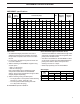
Specifications


6
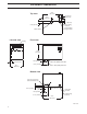
VAPORMIST piping
Water makeup piping may be of any code-approved
material (copper, steel, or plastic). The final connection
size is ¼" NPT (DN8). In cases where water hammer
may be a possibility, a shock arrestor should be
considered. Water pressure must be between 25 psi
and 80 psi (175 kPa and 550 kPa).
Drain piping may be of any code-approved material
(copper, steel, or plastic rated for 212 °F [100 °C]
minimum). If drainage by gravity is not possible, use a
small pump (DRI-STEEM Part No. 400280).
The final connection size is ¾" NPT (DN20) for tank
and frame drains. This connection size should not be
reduced. (See the drawings on the following pages for
proper drain piping configurations.) The tank drain
should be piped separately from the frame drain, as
shown, to prevent backflow of drain water into the
humidifier cabinet.
Install a union in the water supply line as shown in
the drawings on the next two pages to allow tank
removal.
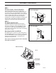
Locating and mounting the humidifier
The VAPORMIST humidifier is designed to attach to
the wall with lag bolts, and it should be installed in a
space located near an air duct system, unless using a
Space Distribution Unit (SDU) for dispersion.
Consider the following when selecting the location of
the humidifier:
• Convenient access to duct
• Electrical and plumbing connections
• Required clearances
• External water seal requirements
Electrical power supply, water makeup piping and drain
piping must also be considered. Electrical power
supply connections are made at the lower or upper
right rear corner of the unit. Water makeup and drain
piping connections are made at the lower left rear
corner.
When mounting on a stud wall (studs 16" [406 mm] on
center), locate studs and position lag bolts in place so
that each of the bolts will center on a stud. Mark hole
locations and predrill ¼" (6 mm) diameter pilot holes
using mounting template on the VAPORMIST box.
Secure frame to wall with lag bolts provided.
For hollow block or poured concrete wall mounting,
position template in place and mark the holes. Drill
appropriate pilot holes for two 3/8" (10 mm) toggle
bolts or two 3/8" (10 mm) machine bolt lead anchors.
Secure frame in place.
VAPORMIST
®
MOUNTING AND PIPING
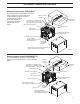
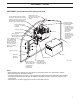
Clearance recommendations
For recommended service and maintenance purposes,
maintain the following clearances:
Top (when SDU is not
mounted directly above the
VAPORMIST): 18" (460 mm)
Floor: 24" (610 mm)
Supporting
wall
Left side:
12" (305 mm)
DC-1201
Right side electrical
controls: 36" (915 mm)
Front: 36" (915 mm)
Secured to
supporting
wall
To dispersion
unit
VM99-C-0302.pdf 6 11/19/2009 9:51:30 AM