READ AND SAVE THESE INSTRUCTIONS ® VAPORMIST and VAPORMIST DI ELECTRIC STEAM HUMIDIFIERS Installation, Operation and Maintenance Manual For toll-free technical support call 1-800-328-4447
TABLE OF CONTENTS To the purchaser and installer Thank you for purchasing our VAPORMIST® humidifier. We have designed and built this equipment to give you complete satisfaction and trouble-free service for many years. Familiarizing yourself with this manual will help ensure proper operation of the equipment for years to come. This manual covers the installation and maintenance procedures for both the VAPORMIST and VAPORMIST DI humidifiers.
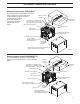
VAPORMIST® HUMIDIFIER OVERVIEW Standard water models (VAPORMIST) The standard water VAPORMIST unit requires water conductivity of at least 100 µS/cm Electrical conduit (2 grains/gallon) to operate. It will not knockouts operate with water treated by reverse osmosis or 1½" (DN40) or 2" (DN50) flexible vapor hose, pipe or tubing connects deionization processes to dispersion tube(s) or to an SDU (see DI water model below).
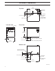
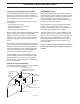
VAPORMIST® DIMENSIONS 24.2" (614 mm) Top view 2" (50 mm) 10.9" (276 mm) 2" (50 mm) 1" (25 mm) 2.25" (57 mm) Power wiring knockout Control or SDU wiring knockout Steam outlet Front view Left side view Venting 18.6" (472 mm) 2.25" (57 mm) 16.1" (409 mm) 1.50" (38 mm) 5.75" (146 mm) ¾" NPT (DN20) frame drain ¾" NPT (DN20) tank drain Bottom view 0.50" (13 mm) hole in base for water fill line 0.75" (19 mm) 0.63" (16 mm) 2.25" (57 mm) Power wire knockout 1.
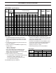
VAPORMIST® SPECIFICATIONS VAPORMIST specifications VM model number Steam capacity lbs/hr Current draw (amps) kg/h Single-phase kW Shipping weight ‡ Operating weight ‡ Three-phase 120V 208V* 240V* 480 † 600V † 208V* 240V † 480V † 600V † lbs kg lbs kg 2 6 2.7 16.7 9.6 8.3 4.2 3.3 -- -- -- -- 2 80 36 95 43 4 12 5.4 33.3 19.2 16.7 8.3 6.7 16.7** 14.4** 7.2** 5.8** 4 80 36 95 43 6 18 8.2 -- 28.8 25.0 12.5 10.0 25.0** 21.7** 10.8** 8.
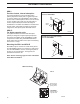
VAPORMIST® MOUNTING AND PIPING Locating and mounting the humidifier VAPORMIST piping The VAPORMIST humidifier is designed to attach to the wall with lag bolts, and it should be installed in a space located near an air duct system, unless using a Space Distribution Unit (SDU) for dispersion. Water makeup piping may be of any code-approved material (copper, steel, or plastic). The final connection size is ¼" NPT (DN8).
VAPORMIST® PIPING VAPORMIST (standard water) field piping overview ¼" NPT (DN8) connection to water supply line; water pressure must be between 25 psi and 80 psi (175 kPa and 550 kPa); water conductivity minimum 2 grains/gallon (100 µS/cm) Steam vapor hose (maximum run 10' [3 m]). May also use pipe or tubing.
VAPORMIST® PIPING VAPORMIST DI (deionized/reverse osmosis water) field piping overview ¼" NPT (DN8) connection to water supply line; water pressure must be between 25 psi and 80 psi (175 kPa and 550 kPa); water chloride content must be less than 3 ppm; first 3' (1 m) of supply line must be rated for 212 °F (100 °C) Steam vapor hose (maximum run 10' [3 m]).
VAPORMIST® WIRING VAPORMIST wiring Field wiring requirements All wiring must be in accordance with all governing codes, and with the VAPORMIST or VAPORMIST DI wiring diagram. The diagrams are located inside the removable subpanel cover on the right side of the humidifier cabinet. Power supply wiring must be rated for 105 °C.
VAPORMIST® DISPERSION SDU-I: Provides instant, internal absorption The Space Distribution Unit Internal Absorption (SDU-I) disperses humidity with no visible vapor trail or wetness, making the VAPORMIST® with an SDU-I ideal for use in finished spaces. When room RH is 45% or less, the SDU-I fan mixes room air and steam to ensure complete absorption before discharge as humidified air.
VAPORMIST® DISPERSION Installing Space Distribution Units (SDUs) When performing VAPORMIST maintenance Provide at least 6" (150 mm) clearance on each side of the SDU. If the SDU-E or SDU-I is installed immediately above the VAPORMIST, disconnect both hose clamps on the steam hose, grip the hose and rotate it to break it loose from the tubing, and then slide the hose up onto the SDU steam tube until sufficient clearance is provided to move the tank.
VAPORMIST® DISPERSION SDU-E: Rise, throw and spread The table below lists the minimum rise, throw and spread non-wetting distances for SDU-E area-type humidifiers at 40%, 50% and 60% RH in the space. Surfaces cooler than ambient temperature, or objects located within this minimum dimension, may cause condensation and dripping. To avoid steam impingement on surrounding areas, observe the minimum non-wetting distances in the table below.
VAPORMIST® DISPERSION Single tube without condensate drain Duct Single dispersion tube without condensate drain Interconnecting plumbing may be hose, tubing or hard pipe. Insulate tubing and hard pipe to reduce steam loss. VAPORMIST humidifier Mounting nut 3/8" - 16 (M10) Pitch: 1/8"/ft (1%) Secure and seal escutcheon plates Tube pitch: 2"/ft (15%) 90° long sweep or two 45° elbows Dispersion tube escutcheon plate 3.25" DC-1447 (82.5 mm) 3.25" (82.5 mm) See the first note below.
VAPORMIST® DISPERSION Single tube with condensate drain Single dispersion tube with condensate drain Interconnecting plumbing may be hose, tubing or hard pipe. Insulate tubing and hard pipe to reduce steam loss. Duct Secure and seal escutcheon plates Pitch: 1/8"/ft (1%) 90° long sweep or two 45° elbows See the first note below.
VAPORMIST® DISPERSION RAPID-SORB dispersion assembly Position L-bracket so that flange is upstream of dispersion tubes. Drawing shows L-bracket positioned for airflow back to front. L-bracket Air Dispersion tube flo w Duct Point tubelets perpendicular to airflow 90° long sweep or two 45° elbows Secure and seal escutcheon plates Slip coupling or hose cuff Support bracket that has 0.
VAPORMIST® DISPERSION Drip tee installation Install a drip tee as shown below when the humidifier is mounted higher than the dispersion device, when interconnecting hose or piping needs to go over an obstruction, or when interconnecting piping runs are long. IMPORTANT: Vapor hose must be supported to prevent sagging or low spots. 90° long sweep or two 45° elbows Pitch: 1/8"/ft (1%) Obstruction Dashed lines indicate provided by installer.
VAPORMIST® DISPERSION Maximum steam carrying capacity and length of interconnecting vapor hose, tubing and pipe* Copper or stainless steel tubing and Schedule 40 steel pipe Vapor hose Hose I.D. Maximum capacity Tube or pipe size*** Maximum length** Maximum developed length† Maximum capacity inches DN lbs/hr kg/h ft m inches DN lbs/hr kg/h ft m 1½ 40 150 68 10 3 1½ 40 150 68 20 6.1 2 50 250 113 10 3 2 50 220 100 30 9.
VAPORMIST® START-UP AND OPERATION Introduction After the system has been properly installed and connected to both electrical and water supplies, it may be started. Start-up and checkout procedures Mounting Check mounting to verify that the unit is level and securely supported before filling with water. Piping Verify that all piping connections have been completed as recommended and that water pressure is available. • Standard makeup water piping (VAPORMIST models) Use cold or hot makeup water.
VAPORMIST® START-UP AND OPERATION VAPOR-LOGIC®3 control VAPOR-LOGIC3 is the standard controller for the VAPORMIST. For more information regarding the operation of the VAPOR-LOGIC3 microprocessor, see the VAPOR-LOGIC3 Installation, Operation and Maintenance Manual. Control system start-up/checkout 1. Confirm that proper grounding and an approved earth ground are provided. 2. Confirm that the control signal connected to the VAPOR-LOGIC3 system is compatible with the VAPOR-LOGIC3 program.
VAPORMIST® MAINTENANCE The best way to determine how often your particular system will need maintenance is to remove the cover and inspect it after its first three months of duty. Potable water carries a variety of minerals and other materials in a mix that varies from location to location. This variation in water quality, combined with the hours of operation and duty cycle, will determine your own unique maintenance schedule. Water quality makes a difference 1.
VAPORMIST® MAINTENANCE Standard water models (VAPORMIST, continued) Off-season shut-down procedure 1. Switch off electrical power. 2. Loosen the four cover bolts and remove the cover assembly from the tank. 3. Clean the tank interior using a putty knife or similar flat instrument. 4. Unplug probe plug assembly. Leave ground wire connected to tank. Unscrew the probe rod assembly and clean the plastic probe housing, ensuring that all passageways are clear.
VAPORMIST® MAINTENANCE DI water models (VAPORMIST® DI) The VAPORMIST DI unit uses DI/RO water. Because these water types are mineral-free, cleaning the evaporating chamber should not be necessary. However, there are some maintenance steps that should be followed to ensure all parts of the unit are in working order 4. Inspect the valve inlet for debris. 5. Check the operation of the float valve and the condition of the float seat. 6.
VAPORMIST® TROUBLESHOOTING GUIDE Troubleshooting guide for standard water models PROBLEM POSSIBLE CAUSE RECOMMENDED ACTION Incorrect or nonexistent supply voltage to unit Check main line safety switch. Check main line fuses. Check for proper supply voltage. Incorrect or nonexistent control voltage Reset control transformer circuit breaker. Check for 24 VAC control circuit voltage at T-1 and T-2 on the control board. Humidistat not calling Set humidistat to call. Inspect for faulty humidistat.
VAPORMIST® TROUBLESHOOTING GUIDE Troubleshooting guide for DI water models PROBLEM Humidifier will not heat. Humidifier will not fill. Humidifier does not stop filling. Reduced or no output even though water is at the proper level 24 POSSIBLE CAUSE RECOMMENDED ACTION Control transformer Reset control transformer circuit breaker. Humidistat is not calling Set humidistat to call. Inspect for faulty humidistat. Safety controls open Check safety controls, airflow switch, high limit humidistat, etc.
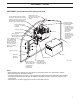
VAPORMIST® REPLACEMENT PARTS VAPORMIST® standard water model VAPORMIST DI model Note: Refer to the tables on the next page for replacement part numbers.
VAPORMIST® REPLACEMENT PARTS VAPORMIST® replacement parts (refer to the drawing on previous page) No. Description Qty. Part No. No. Description Part No. 1 Head bolt, large Phillips, ¼ - 20 X 1" 4 700300-013 19 Washer, No.
VAPORMIST® REPLACEMENT PARTS Space Distribution Unit, external absorption (SDU-E) OM-1503 No. Description Qty. Part. No. 1 Shroud 1 330001-003 2 Blower, SDU99 external assembly 1 * 3 Switch, airflow 1 406190 4 Screw, 8-32 x 1/2" PHMS Philips 4 700170-007 5 Nut retainer, 8-32 4 409593-001 6 Cap, black 4 409593-002 Dispersion chamber for SDU with 1½" outlet 1 160445-001 Dispersion chamber for SDU with 2" outlet 1 160445-002 7 * This is an assembly of multiple parts.
VAPORMIST® REPLACEMENT PARTS Space Distribution Unit, internal absorption (SDU-I) OM-1504 No. Description Qty. Part. No. 1 Shroud 1 330001-002 2 Blower, SDU99 external assembly 1 * 3 Switch, airflow 1 406190 4 Screw, 8-32 x 1/2" PHMS Philips 6 700170-007 5 Nut retainer, 8-32 6 409593-001 6 Cap, black 6 409593-002 7 Tubelet, 0.375" x 0.375", molded 44 310280-006 * This is an assembly of multiple parts. Contact your DRI-STEEM representative to order parts.
VAPORMIST® REPLACEMENT PARTS VAPORMIST® subpanel with SSR OM-213-4 No. 1 Description Subpanel, VM99 barrier No. Description Qty. Part. No. Qty. Part. No. 1 120801 9 Main board, VL-3 1 408490-001 Display board, VL-3 1 408490-002 DIN rail, 8" long 1 167765-008 10 DIN rail, 10.
VAPORMIST® REPLACEMENT PARTS VAPORMIST® subpanel with SDU OM-1506 No. Description Qty. Part No. No. Qty. Part No.
NOTES 31
TWO-YEAR LIMITED WARRANTY DRI-STEEM Humidifier Company (“DRI-STEEM”) warrants to the original user that its products will be free from defects in materials and workmanship for a period of two (2) years after installation or twentyseven (27) months from the date DRI-STEEM ships such product, whichever date is the earlier.